read the post
using a maplin module as an amplifier espesially driving it from this domestic pest repeler circuit wont get you anywhere ....
it is for shure that input of this module is very well guarded NOT to operate in high frequencies
you have to modifi the input filtering of any amp and out filtering to get closer to what you want
Re: read the post
Even if the output is stated to 25khz?sakis said:using a maplin module as an amplifier espesially driving it from this domestic pest repeler circuit wont get you anywhere ....
it is for shure that input of this module is very well guarded NOT to operate in high frequencies
you have to modifi the input filtering of any amp and out filtering to get closer to what you want
remooving
teh filter of the input or better change it will get you there the amp its shelf my work much higher in frequency than "stated"
teh filter of the input or better change it will get you there the amp its shelf my work much higher in frequency than "stated"
Fasterstill
What voltage swing do you need, and what is the capacitance of the load? Also, do you plan on driving a periodic signal or not? About 2 years ago I designed a +/- 1KV supply to drive piezo drivers for an sonofusion experiment. Depending on your requirements, these circuits may be useful for your application.
JCM
"continuous 8 hour noise test "
What do you think this is? It's a full range signal.
"What voltage swing do you need"
At the risk of repeating myself:
"The real Motorola piezos can handle 14V RMS (about 1W at 20Khz) at frequencies above 5Khz, the cheap copies you find today cannot handle that much."
What do you think this is? It's a full range signal.
"What voltage swing do you need"
At the risk of repeating myself:
"The real Motorola piezos can handle 14V RMS (about 1W at 20Khz) at frequencies above 5Khz, the cheap copies you find today cannot handle that much."
Tryed a sugestion from one of the posters here with a TIP 3055 on the output of the frequency generator unit i mentioned earler but with poor results, no louder than the origional output from the FG modual.
Still looking into this and found these two bits of info that may help push this project along when viewed by someone with more knowledge than me.
http://www.sonitron.be/Media/02AN102.pdf
is this any good ?
http://www.freeinfosociety.com/elec...ldgenerator.pdf
could this work at frequencys say 20khz to 35khz?
also had this feedback:
I think that for your application you don't need an amplifier. All you need is a MOSFET that will switch your piezo load at the requested frequency (i.e. on-off). If you would like to tune the volume, you should reduce the voltage of your power supply.
You may use any MOSFET for 250V. Look at www.IRF.com or simply contact your local electronics store. You connect it as the test circuit suggest.
Use a N channel MOSFET. Connect the Source to ground (-) of the power supply and the 556 chip. the drain would be connected to the (-) terminal of your piezo element and the other side of the Piezo to +200V. The 556 need a low voltage power supply with it's ground connected to the same ground of the 200V supply and the 556 chip. THe output of the 556 should be connected via 1K resistor to the GATE of the MOSFET.
As for the power supply: You need something more robust. Try to find a 200V @ 1.5A power supply. It may be a switch mode power supply.
Any thoughts.
Read the Post
There is a company specializing in high voltage opamps, Apex Microtechnologies, I believe they have app notes on driving piezo transducers.
http://eportal.apexmicrotech.com/mainsite/
Hope this helps.
There is a company specializing in high voltage opamps, Apex Microtechnologies, I believe they have app notes on driving piezo transducers.
http://eportal.apexmicrotech.com/mainsite/
Hope this helps.
when you say no louder... do you have some means to test... cause you cetainly won't hear anything louder....
I know those baby piezo buzzers you get come in diffirent efficiencies from low 70db to over 100db... not familiar with the transducers but would expect something similar....
I know those baby piezo buzzers you get come in diffirent efficiencies from low 70db to over 100db... not familiar with the transducers but would expect something similar....
Nordic said:when you say no louder... do you have some means to test... cause you cetainly won't hear anything louder....
I know those baby piezo buzzers you get come in diffirent efficiencies from low 70db to over 100db... not familiar with the transducers but would expect something similar....
Hi Nordic
I tested at the lowest frequency so i could hear, about 10-12khz.
Also it was tested before and after with a piezo horn not the baby buzzer.
Re: did you try ???
Hi Sakis
Hav'nt been able to modifie the amp i brought as its fully potted, can't get at anything inside. so im trying the simple cheapest ideas first. May very well end up going the route of modifing an amp and any input, sugestions at that point will be greatfully taken 🙂
Spoted this on another thread and wondered what you guys thought?
Would this be loud enougth or could the design be scaled up?
http://img187.imageshack.us/img187/1643/horndogsc9.gif
sakis said:did you try any of the thingsi recomended ?????
Hi Sakis
Hav'nt been able to modifie the amp i brought as its fully potted, can't get at anything inside. so im trying the simple cheapest ideas first. May very well end up going the route of modifing an amp and any input, sugestions at that point will be greatfully taken 🙂
Spoted this on another thread and wondered what you guys thought?
Would this be loud enougth or could the design be scaled up?
http://img187.imageshack.us/img187/1643/horndogsc9.gif
The sonitron amp looks like it fits the requirement. Still, the specs look a little questionable, just how do they get 2A through the 100R series resistor with only 60V ? Anyway, you don't need to drive anything like that amount of current. Hopefully, its tested with highly capacitive loads ...
I guess you could wire a series / parellel array of horns to this amp. 4 horns (2 in parellel / in series) or 9 horns (3 in parellel / in series). Do you have the specification of the horns you actually intend to use ?
I guess you could wire a series / parellel array of horns to this amp. 4 horns (2 in parellel / in series) or 9 horns (3 in parellel / in series). Do you have the specification of the horns you actually intend to use ?
Han'nt settled on a perticular piezo yet stillopen on that one but typical specs seem to be aroundDRC said:The sonitron amp looks like it fits the requirement. Still, the specs look a little questionable, just how do they get 2A through the 100R series resistor with only 60V ? Anyway, you don't need to drive anything like that amount of current. Hopefully, its tested with highly capacitive loads ...
I guess you could wire a series / parellel array of horns to this amp. 4 horns (2 in parellel / in series) or 9 horns (3 in parellel / in series). Do you have the specification of the horns you actually intend to use ?
Specifications
Frequency Response 3kHz - 30kHz
SPL (1W/1m) 100dB
Impedance 1000Ù@1kHz 50Ù@25kHz
voltage seems to be about 14rms 30v max
And yes several people have mentioned the specs on that Sonitron unit. Also had comments on the heat dissipation with that design.
What did you think on the circuit linked in my previous post?
What did you think on the circuit linked in my previous post?
It may work, but i would have the fire extinguisher handy


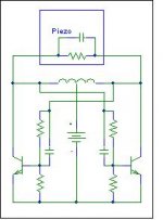
The following would work if only one frequency is needed. It is a classic from RF engineering and it is called a push-pull oscillator. It would use the piezo as part of the resonant tank. The peak output voltage is twice the supply voltage. It could also be done with FETs for instance. Efficiency is best when the devices work in class-C.
If necessary there are also methods that would allow to modulate the frequency.
Regards
Charles
If necessary there are also methods that would allow to modulate the frequency.
Regards
Charles
Attachments
Consider a class-D-like switching output stage, with a LC output filter as usual, but tuned to resonate together with the own capacitance of the piezos in the desired (narrow) frequency range. Such a system may be 90% efficient (electrically), light weight, compact, and will probably produce a lot of sound during a lot of time from a 12V battery...
Still looking for someone to build a circuit to drive piezo at up to 30v from 12v supply.
Any takers?
Please
Any takers?
Please
did you try ???
anything from the things i said ???
cause i actually tryied and works really fine let me know
anything from the things i said ???
cause i actually tryied and works really fine let me know
Still looking for someone to build a circuit to drive piezo at up to 30v from 12v supply.
Why from a 12v supply, is it going to run on (car) batteries ?
30V (rms) = 84V peak to peak, its not impossible but will require an 'invertor' / SMPS if your stuck with a 12V supply.
The ideas put forward of a 'tuned' circuit to drive the transducer are good IF you know exactly what sort of signal you need and it is a continious or pulsed single frequency
hi
yep it would need to run from car battery.
possible use in remote locations, eg field. Not safe having 240v live running around.
yep it would need to run from car battery.
possible use in remote locations, eg field. Not safe having 240v live running around.
- Status
- Not open for further replies.
- Home
- Amplifiers
- Solid State
- looking for someone to build me a high frequency amp