I'm trying to build a second amplification stage for a J201-based buffer, but don't know how to pick out a transistor. The attached circuit models well with a generic PNP model, but looking for small-signal PNP transistors, I can't find any with reasonably linear hFE in the Ic=100uA range. Am I being too picky? Will almost anything work well here?
If possible, I'd like an SOT-23 or SC-70, as this buffer needs to fit inside an XLR plug, and four TO-92s won't fit.
If possible, I'd like an SOT-23 or SC-70, as this buffer needs to fit inside an XLR plug, and four TO-92s won't fit.
Attachments
To answer my own question, I just came across the MPSA92/MMBTA92, which seems to have a pretty smooth hFE vs Ic graph.
Any comments?
Any comments?
Usually at these small currents high beta transistors perform better, Id look at 2n5087/mmbta5087.
Fairchild puts the KSC1845/KSA992 in both thru-hole and SMT packages, which leads me to believe there are long-term plans to keep this product in production.
2SC3324/2SA1312 from Mouser is another possibility.
Dale
2SC3324/2SA1312 from Mouser is another possibility.
Dale
It may be helpful, also, to have a single-die matched pair in an array to make the current-mirror diode from. Does anyone know of any good ones?
It may be helpful, also, to have a single-die matched pair in an array to make the current-mirror diode from. Does anyone know of any good ones?
THAT320 -- i think Mouser has them and they are available as SMT.
THAT3XX devices have a min breakdown of 36V. They come in SO-14 package.....and are not very cheap.
It is a current multiplier, factor of about 6.7.
With modern devices, hFE is not important. You have built an artificial hFE=6.7 device. As long as the hFEs are >>6.7, they hardly matter.
Hmmmm.... your hi-voltage (300V??) parts are awful low-hFE (min 25). 25 is not >> 6.7.
R.G.'s Law: throw in a 5089. 2N5089 min=400 is a popular part. 400 is >> 6.7. It isn't sold under that number in SMD but there are high-hFE SMDs. A moment with OnSemi's awful lister gives:
BC857CL SOT-23-3 PNP 420 800
BC857CW SC-70-3 / SOT-323-3 PNP 420 800
BC858CL SOT-23-3 PNP 420 800
I see others point to '5089 parts in SMD size. Probably all the same part under different historic numbers.
The 857 series has normalized nominal hFE variation 0.9 to 1.0 over the 0.5mA and 3mA spread of your two devices, much less for say 2mA-4mA of your output devices pumping large level. The curve is monotonic rise, which will cancel in push-pull.
Oh, the circuit is not perfect-balance push-pull, but close enough for decently improved linearity. Without doing math, I suspect that if hFE is >100 then JFET nonlinearity will exceed any booster nonlinearity.
The current multiplication will increase output level about 16db.
You do not say, but I assume, the load is a Microphone Amp.
This scheme will not improve sensitivity. It does the same thing as just turning the mike-amp up another 16db. On many mike-amps the noise figure will improve a bit when turned to near maximum gain.
The proposed J201+2K2 (twice) has noise resistance near 6K. Any modern $10 mike preamp has noise resistance near 150r (at high gain). The JFET pair has 6.3 times more hiss than the mike amp.
The circuit gain is undefined. You show 13K load but the mike amp has 100K, 5K, or 1K bias resistors, 200K-2K input impedance. Or if transformer input, it may be 1K at 20Hz but 10K||13K=5K at 200Hz and 30K||13K=9K at 1KHz. That's a 19db rise. Above midrange it will fall due to stray capacitance.
The line impedance is just the load impedance. This "mike" is a current source, well over 10K impedance. (This is true in the original also.) 200 ohm lines are pretty good at absorbing external interference; 1K and up not so good. You do however gain a little S/N by increased current and thus level.
The proper answer is to replace the J201s with FETs six times fatter. Six J201 parallel (each side) works; there are many fatter JFETs which will do it in one device (each side).
Oh, and reduce the huge 2K2 resistors to like 330r.
The fatter JFETs will also have lower noise voltage.
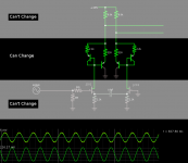
But if the lower-third is "Can't Change", then nothing will improve the hiss performance and adding gain in the shell is no better than adding gain at the mike-amp knob.
With modern devices, hFE is not important. You have built an artificial hFE=6.7 device. As long as the hFEs are >>6.7, they hardly matter.
Hmmmm.... your hi-voltage (300V??) parts are awful low-hFE (min 25). 25 is not >> 6.7.
R.G.'s Law: throw in a 5089. 2N5089 min=400 is a popular part. 400 is >> 6.7. It isn't sold under that number in SMD but there are high-hFE SMDs. A moment with OnSemi's awful lister gives:
BC857CL SOT-23-3 PNP 420 800
BC857CW SC-70-3 / SOT-323-3 PNP 420 800
BC858CL SOT-23-3 PNP 420 800
I see others point to '5089 parts in SMD size. Probably all the same part under different historic numbers.
The 857 series has normalized nominal hFE variation 0.9 to 1.0 over the 0.5mA and 3mA spread of your two devices, much less for say 2mA-4mA of your output devices pumping large level. The curve is monotonic rise, which will cancel in push-pull.
Oh, the circuit is not perfect-balance push-pull, but close enough for decently improved linearity. Without doing math, I suspect that if hFE is >100 then JFET nonlinearity will exceed any booster nonlinearity.
The current multiplication will increase output level about 16db.
You do not say, but I assume, the load is a Microphone Amp.
This scheme will not improve sensitivity. It does the same thing as just turning the mike-amp up another 16db. On many mike-amps the noise figure will improve a bit when turned to near maximum gain.
The proposed J201+2K2 (twice) has noise resistance near 6K. Any modern $10 mike preamp has noise resistance near 150r (at high gain). The JFET pair has 6.3 times more hiss than the mike amp.
The circuit gain is undefined. You show 13K load but the mike amp has 100K, 5K, or 1K bias resistors, 200K-2K input impedance. Or if transformer input, it may be 1K at 20Hz but 10K||13K=5K at 200Hz and 30K||13K=9K at 1KHz. That's a 19db rise. Above midrange it will fall due to stray capacitance.
The line impedance is just the load impedance. This "mike" is a current source, well over 10K impedance. (This is true in the original also.) 200 ohm lines are pretty good at absorbing external interference; 1K and up not so good. You do however gain a little S/N by increased current and thus level.
The proper answer is to replace the J201s with FETs six times fatter. Six J201 parallel (each side) works; there are many fatter JFETs which will do it in one device (each side).
Oh, and reduce the huge 2K2 resistors to like 330r.
The fatter JFETs will also have lower noise voltage.
But if the lower-third is "Can't Change", then nothing will improve the hiss performance and adding gain in the shell is no better than adding gain at the mike-amp knob.
The source is a passive bass with humbuckers, so very low-level, high-impedance source. The original purpose of that buffer was to reduce the effects of cable capacitance on the sound from the bass/guitar, so the JFET part of the amp is built into a Neutrik 1/4" plug.
When I plug that cable into my Shure X2u, I get a lot of hiss, that I suspect is coming from the phantom power supply in the X2u. I was hoping that adding gain like this would increase the PSRR of the amplifier. Turning the gain up on the X2u produces lots of hiss, and it also picks up a local AM radio station when I grab the tip of the 1/4" plug (not completely unexpected).
When I plug that cable into my Shure X2u, I get a lot of hiss, that I suspect is coming from the phantom power supply in the X2u. I was hoping that adding gain like this would increase the PSRR of the amplifier. Turning the gain up on the X2u produces lots of hiss, and it also picks up a local AM radio station when I grab the tip of the 1/4" plug (not completely unexpected).
2n5089/MMBT5089 has C-E voltage of 30V, which I don't think will cut it here. The MMBT5087 looks like it could work. Min hFE is 250, which seems to be >>6.7.
Phantom supply should not hiss. There's 50uFd or more on the straight 48V, unless Shure did something odd or the Phantom is sick.
The "30V" rating is perhaps not a problem. It won't explode: 48V through 6K8 can only put 85mW in the transistor worst-case. If current were very low, it might limit positive swing, but swing must be small or you would not have hiss issues. And you should probably be flowing enough current to get the XLR pins down near 24V.
Finally, I bet 99% of the '5089s you try have breakdown well over 40V, though I agree it is bad habit to bet on parts beating their specs.
> very low-level, high-impedance source
It should not be a real hiss problem. Does the bass play OK/clean on short cable into a good amp?
> picks up a local AM radio
As you say, no surprise; it is conventional to have an R-C between instrument and first gain stage just-in-case you get a gig under a radio tower or a CB-ridden trucker's bar.
- Status
- Not open for further replies.
- Home
- Amplifiers
- Solid State
- Looking for small-signal PNP