I have only released two versions, the original TSE and the TSE-II. Both have the same audio path. The TSE-II replaced the original TSE when Foxconn bought Sharp Semiconductor and killed off all of the non profitable chips including the voltage regulator used in the original TSE. The TSE-II incorporated most of the changes requested here when I redesigned the board to use an LDO regulator from Microchip.Tubelab SE ? There appear to be several versions of this beast.
Unfortunately, there are at least two people in countries where US law doesn't apply that are selling copies of my designs or posting them to board sharing sites with a different PCB layout but using the Tubelab name. These are NOT my PCB layout designs
. I have actually received emails asking me to critique their PCB design which I do not answer. Let's just say that I wouldn't do it that way. My sales have been declining over the last few years, but with only 12 orders so far this year, which does not cover the fixed cost of operations, Tubelab Inc, the company will likely cease operations this year.
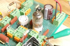
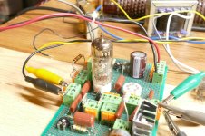
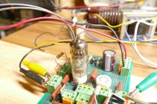
I don't have the 6EJ7 numbers handy at the moment, but the best results were seen with that little skinny 7 pin tube seen in the picture in post #14. Numbers around 0.2% were seen with the best tube out of about 10 that I have. I won't reveal the type number until I can get a few more, but the oddball 7 pin TV IF amp tubes seem to beat the usual 9 pin TV IF amp tubes like the 6EJ7, 6JC6 and 6JD6 in the post #14 circuit.I have done some testing with a 6EJ7 as an UNSET driver, CCS loaded, was able to get 50V+ RMS on a 10K load, 1% THD, cascade harmonic profile. I was very impressed. George has better results, less THD.
Hi @Tubelab_com , it has become increasingly a hassle to send PCBs between countries. I ordered as much as I could from you last time, hoping for a long life to cover my wish list, just to keep the shipping, VAT and admin charges down to a minimum compared with the costs of the fruits of your toils, the PCBs.My sales have been declining over the last few years, but with only 12 orders so far this year, which does not cover the fixed cost of operations, Tubelab Inc, the company will likely cease operations this year.
Since the manufacturing is centralised in yet another country, there must be another model where you are compensated and overheads are minimised?
I also tried EF183s (variable mu versión of the EF184), expecting pretty bad results, but they performed exactly like the EF184.
I have seen similar results. The 6EJ7 / EF184 is a $4 tube, but the 6EH7 / EF183 is on the 10 for $7.50 list, so I bought 100 of them for $50. They all worked much like the 6EJ7 in an average audio amp unless you did push them to 50 volts RMS output.I also tried EF183s (variable mu versión of the EF184), expecting pretty bad results, but they performed exactly like the EF184.
I was a TV repair guy when I was still in high school. The shop was a Philco authorized warranty repair shop, so we got all the service bulletins. It seems that the US made 6EJ7s and the European EF184 were different at the time (late 1960's). We were told to use only US made RCA tubes in the Philco 25 inch color sets. It seems that their IF amp was on the verge of oscillation and the Euro tubes pushed them over the edge.
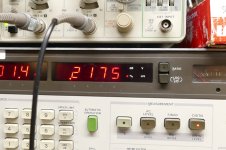
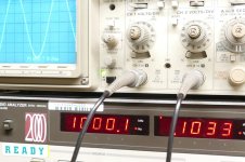
I hooked up the old board and tested it with the tube that was in it. I could get 0.4% THD at 50Vrms with a little tweaking on the bias pot. I then picked up a random 6AK5 tube that was on the bench and plugged it in. A turn of the bias pot brought similar numbers.
Attachments


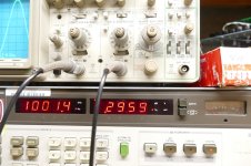

A bit of digging through boxes turned up a NOS Amperex EF184 and a NOS Amperex EF183. I plugged them in and twisted the pots.......
I need to go over my test board and get the current parts values for what's actually in the board.
I need to go over my test board and get the current parts values for what's actually in the board.
Attachments
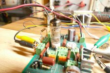
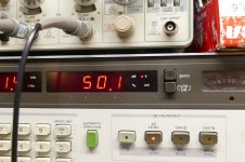
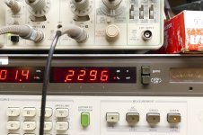
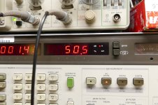
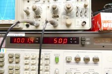
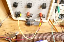
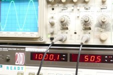
I just realized that I made a mistake, and my previous numbers are slightly in error. I added the fat yellow jumper wire to ground the heater supply which had been previously floating and the THD numbers dropped into the under 0.2% region that I remember. The EF183 is still in the socket too.
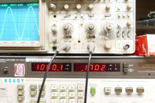
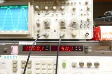
The 7 pin tube brings a slightly lower number.
The 7 pin tube brings a slightly lower number.
Attachments
The schematic of my board is shown in the "Unseturator 5-12-24.gif" picture in post #14. I have seen similar things called gyrator, and is does indeed have some inductor like properties.
The "magic" is performed by "bootstrapping" the plate load resistor. The AC signal voltage that appears on the plate of the tube is applied to the gate through capacitor C2. C2 and R16, R14 and R17 form a high pass filter rolling off the bootstrapping at very low frequencies. With nearly equal AC signal voltages appearing on both ends of R2, hardly any signal current flows through the resistor, so the tube sees a nearly infinite load impedance above the filter frequency. R13 is a gate stopper, but R16 and the parallel combination of R14 and R17 are i parallel with this nearly infinite load impedance. I have used a 2 meg pot for R16 in a guitar amp and this results in a variable gain stage which is adjustable from very low gain to extremely high gain. In reality the gain is limited by microphonics in the vacuum tube itself. Little guys like the 6AK5 are usable with gain in excess of 1000, bit larger pentodes like the octal 6SJ7 can become "howlers" if pushed too hard.
One can use a CCS in the plate of a pentode to get nearly infinite gain with the same issues. Beyond microphonics, you will get instability since the pentode itself is a constant current device, and using two CCS's in series doesn't work, as the strongest one will saturate. The "cheat" here is to make the "load" CCS intentionally lousy with a resistor across it. In this case the u-follower (source) output can be used. If you want to intentionally turn audio into square waves, this is the way to do it.
Right, but then we have the plate to g1 negative feedback in the UNSET setup, which basically solves this problem, correct?One can use a CCS in the plate of a pentode to get nearly infinite gain with the same issues. Beyond microphonics, you will get instability since the pentode itself is a constant current device, and using two CCS's
The negative feedback to G1 does produce triode like curves. These curves can be varied from pentode like to curves that pass for a real triode. This depends on the amount of feedback being applied. The circuit shown in post #14 uses a tiny amount of feedback to G1 as the resistor ratio is 1800K to 27K or 1.5%. This just lowers the THD a bit over the same tube in pure pentode. I usually run 300K to 30K in a sweep tube output stage which is 10% feedback. This results in realistic triode curves.
The picture is from some curves drawn back in 2018 by hand with variable power supplies on a small 6GF5 sweep tube in UNSET with the 300K - 30 K feedback pair. Ancient analog power supplies were used which is the reason for the imperfections in the curves. The circuit also incorporates an RC network from grid to ground. R9 can be a pot to allow for continuous adjustment from pentode to triode curves. It was not present when the curves posted were made. It is a valuable knob to have in a guitar amp though.
The picture is from some curves drawn back in 2018 by hand with variable power supplies on a small 6GF5 sweep tube in UNSET with the 300K - 30 K feedback pair. Ancient analog power supplies were used which is the reason for the imperfections in the curves. The circuit also incorporates an RC network from grid to ground. R9 can be a pot to allow for continuous adjustment from pentode to triode curves. It was not present when the curves posted were made. It is a valuable knob to have in a guitar amp though.
Attachments

I used 330K to 10K when testing the EF184. I'll try less feedback to see what happens.I usually run 300K to 30K in a sweep tube output stage which is 10% feedback. This results in realistic triode curves.
- Home
- Amplifiers
- Tubes / Valves
- Looking for more gain from my tubelab SE