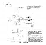
I don't see where you get the 10V. The 10V Zener is there to protect the LED's, which are the real bias setters. The LED's and resistors are there to develope a potential of 6V, which should set the "current" at 45mA.
I may well have missed something (I usually have), can you clarify.
Shoog
I may well have missed something (I usually have), can you clarify.
Shoog
I got the 10V from the 10V zener and didn't pay enough attention.
Yeah, so if you're using red LEDs you'll get 5.1V plus that little bit from the 18 ohm resistors - a little more if you use a colour with a shorter wavelength.
Yeah, so if you're using red LEDs you'll get 5.1V plus that little bit from the 18 ohm resistors - a little more if you use a colour with a shorter wavelength.
The $6,000 question is do you think it will perform adequately for this application. It should be very stiff, but I have a nagging feeling that I just haven't taken everything into account.
Shoog
Shoog
I'm far from the most experienced set of eyes around here, and I often miss things as well. From my current understanding of this type of circuit, the upper valve acts at a constant current source by virtue of applying the signal voltage on the other side of the resistor, bootstrapping it into appearing to be much larger than its actual value. By using LED bias, the resistance which can be bootstrapped is only the slope resistance of the LEDs and the 18R resistors. Boring old resistors may in fact perform better in this application. Of course what I'm saying here may be total rubbish - you really need someone more experienced to comment.
Have a look at Pete Millett's Low-m Preamp for his pentode CCS using EL34s.
Have a look at Pete Millett's Low-m Preamp for his pentode CCS using EL34s.
That exactly the thoughts I was having regarding the use of LEDs, I have done a bit more reading around the subject and think I understand it a bit better now. I have a good circuit to base a new design on and will post tonight.
Thanks for the input.
Shoog
Thanks for the input.
Shoog
Here you go with the new design.
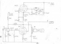
This should run the TT21's very cool, but should perform well.
The capacitance multiplier on the screen should work OK and save me having to get some very expensive 750V smoothing caps.
As a matter of interest, I have just converted the CCS on my cascode preamp to LED fixed bias. the CCS is on the bottom of the stack. Sounds great, certainly an improvement on the resistor I had before. My scope on the top of the LED shows a flat voltage at the top of the LED.
Attachments
I have been thinking more on the design of the CCS, the choice of transistor is proving more technically demanding than I anticipated. It needs to combine the qualities of high voltage (at least 800V to take account of the whole circuit charging up from ground), and also high gain. They don't make such transistors !!
Also it needs some capacitance before and after the transistor.
My brain hurts
When I do eventually get this CCS cracked, it turns out I can provide a seperate screen supply for the 807's by using the 300-0-300V windings, already got that bit designed.
Shoog
Also it needs some capacitance before and after the transistor.
My brain hurts
When I do eventually get this CCS cracked, it turns out I can provide a seperate screen supply for the 807's by using the 300-0-300V windings, already got that bit designed.
Shoog
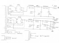
So here is the final plan. Basically it’s the RH807 SE but with a few modifications. The screens of the 807’s have their own supply which generates a 250V reference. It also is tapped off for the 300V driver supply. Because I am using parafeed the 807 cathode bypass cap shouldn’t be necessary. Driver tube has a Red LED to provide fixed bias, as against the original scheme which uses a 300R resistor. I have tried LED fixed bias on my preamp and like the sound of it.
Very simple really. I have most of the bits to implement it.
Any comments, suggestion or criticisms.
Shoog
Very simple really. I have most of the bits to implement it.
Any comments, suggestion or criticisms.
Shoog
Attachments
Shoog said:Because I am using parafeed the 807 cathode bypass cap shouldn’t be necessary.
To do away with the bypass cap, I think that you need to connect your parafeed cap at the top of the cathode resistor.
...read that somewhere.

To do away with the bypass cap, I think that you need to connect your parafeed cap at the top of the cathode resistor.
Sounds logical, anyone care to confirm that.
Shoog
Sounds logical, anyone care to confirm that.
Shoog
I withdraw my previous statement. Since the tube is loaded with a ccs, you don't need the bypass cap... according to Gary P.
I think that, with other parafeed cct's, bringing the parafeed cap to the top of the cathode does away with the need for a bypass cap...I'm still trying to find that reference.
Since the tube is loaded with a ccs, you don't need the bypass cap... according to Gary P. I think that, with other parafeed cct's, bringing the parafeed cap to the top of the cathode does away with the need for a bypass cap...I'm still trying to find that reference.
Your grid leak resistor for the TT21 is missing (replaced with a short) It won't work this way.
Cathode bypass capacitors are never strictly necessary, but a shunt feed output stage is not immune to the requirement of being fed with a low impedance. The m of the 807 in fixed screen mode is very high (as with all pentodes/beam tetrodes). It will increase its effective anode resistance by a factor of Rk x m, which is bad for output impedance and bandwidth. Returning the 4mF cap to the cathode should solve this problem.
Cathode bypass capacitors are never strictly necessary, but a shunt feed output stage is not immune to the requirement of being fed with a low impedance. The m of the 807 in fixed screen mode is very high (as with all pentodes/beam tetrodes). It will increase its effective anode resistance by a factor of Rk x m, which is bad for output impedance and bandwidth. Returning the 4mF cap to the cathode should solve this problem.
your grid leak resistor for the TT21 is missing (replaced with a short) It won't work this way
It is there, but easy to miss. It is a 200R resistor.
The issue with the high resistance of the 807 is addressed by Alexsanders Kitic's design. The 100K resistor between the anodes of the ECC81 and the 807 serves to lower the effective impedence by a feedback mechanism. I am basing this statement on Mr Kitic explanation. The 807 is behaving something between a triode and a tetrode, with an anode resistance somewhere between the two. This is the "partial Feedback mechanism" which has been discussed elsewhere. This is the whole reason why I am basing my design upon Mr Kitic's RH807 SE.
If returning the 4uf parafeed cap to the cathode of the 807 will help matters then I am willing to try it. My understanding would be that this would introduce another element of feedback on top of the designed 100K feedback resistor, which is not necissarily desirable. Is this correct ?
Shoog
Mr Kitic feeds his 807 screen with just a 10K resistor from the B+, maybe this is a deliberate use of another intermediate behaviour between a triode and a tetrode ? I set out to improve on the behaviour of this arrangement, but maybe i've missed the point.
Shoog
Shoog
Shoog said:your grid leak resistor for the TT21 is missing (replaced with a short) It won't work this way
It is there, but easy to miss. It is a 200R resistor.
Believe me, it's missing alright. The 200 ohm resistor is a gridstopper. The grid leak resistor should be placed from this gridstopper to the junction between the 720 ohm and 1.4K resistors.
Shoog said:The issue with the high resistance of the 807 is addressed by Alexsanders Kitic's design. The 100K resistor between the anodes of the ECC81 and the 807 serves to lower the effective impedence by a feedback mechanism. I am basing this statement on Mr Kitic explanation. The 807 is behaving something between a triode and a tetrode, with an anode resistance somewhere between the two. This is the "partial Feedback mechanism" which has been discussed elsewhere. This is the whole reason why I am basing my design upon Mr Kitic's RH807 SE.
The shunt feedback will reduce the output impedance of the output stage, the degree to which it does this is dependant on the feedback fraction, and the gain of the output stage. The resistive loading Mr. Kitic uses for the driver, and the fact that the driver valve is a triode means that the feedback fraction is likely to be significantly less than unity. Furthermore, leaving the cathode resistor unbypassed will both reduce gain (thus reducing the amount of shunt feedback applied) and increase the open-loop output impedance. For the lowest possible output impedance, the method of using the feedback resistor as the DC and AC path (as outlined in Mr. Broskie's article on this subject) would be preferable, as would returning the "parafeed" DC blocking capacitor to the cathode of the 807.
Shoog said:If returning the 4uf parafeed cap to the cathode of the 807 will help matters then I am willing to try it. My understanding would be that this would introduce another element of feedback on top of the designed 100K feedback resistor, which is not necissarily desirable. Is this correct?
Yes, you should return the DC blocking capacitor to the cathode of the 807.
Shoog said:Mr Kitic feeds his 807 screen with just a 10K resistor from the B+, maybe this is a deliberate use of another intermediate behaviour between a triode and a tetrode ? I set out to improve on the behaviour of this arrangement, but maybe i've missed the point.
The arrangement of local feedback around the output stage does not create characteristics intermediate between a pentode and triode (look for distributed-load/ultra-linear amps for that), but simply a valve exhibiting pentode characteristics with a large proportion of its output returned to its input (i.e. feedback). If you want triode characteristics, strap it as a triode - 807s do make excellent triodes.
The method of using a simple unbypassed dropping resistor to provide the screen supply is less than optimal. Quoting the STC datasheet for the 807: "In cases where the screen voltage is lower than the plate voltage it should be obtained from a potentiometer between the HT line and chassis, adequately by-passed to AF signals and not by means of a series resistor"
In tetrode/pentode amplifiers, the screen voltage is the most sensitive supply voltage. Where I haven't been lazy and just used the same voltage for screen and anode, the preferable option would be a regulator (probably a simple one using a 317 IC). They did not have this option back in the heyday of valves, so they did their best by using a potential divider from B+(HT) to earth(chassis), bypassed by a capacitor to make it essentially invisible to AC. Of course the DC draw of the screen varies with signal, so the DC screen voltage bobs up and down with the DC current draw. Using a potential divider decreases this somewhat in comparison to a simple dropping resistor, but nowadays we can do much better.
I have just read a Paramour article which suggests that returning the output transformer to the cathode will indeed result in improved bass. It also suggests that the cathode bypass cap is still needed for bias stability, but since the CCS should be doing a much better job in this department than a choke, I think I will risk it without.
It also pointed out a fundamental mistake I had made. The Parafeed cap should be located at the anode of the 807, otherwise the transformer is carrying the whole 350V. In a fault situation this would be very dangerous. Simply shifting the cap to the anode keeps the transformer at low potential.
Indeed the grid leakage resistor is missing, a simple copying mistake on my part. Still if it hadn’t been spotted at this stage it would probably have made it to the build, so thanks.
Shoog
I was under the impression that it doesn't make any difference which end of the OPT you put the parafeed cap -- you get the same results.
Can you point out the article?
dave
Can you point out the article?
dave
- Status
- Not open for further replies.
- Home
- Amplifiers
- Tubes / Valves
- Looking for KT88 circuits.