Shoog, it shouldn't be that hard to distinguish between an 807 and TT21 visually. Firstly they have different bases. The TT21 has an IO (International Octal) base - the one with spaces for eight pins and a centre spigot. The 807 has a UX5 base - five pins and no centre spigot.
Furthermore, they look different.
TT21 on left, and 807 on the right.
Anyway, if you have TT21s which are still good, there is no need to use them in a 1kV circuit.... and no need for silicon rectifiers.
Furthermore, they look different.
An externally hosted image should be here but it was not working when we last tested it.
An externally hosted image should be here but it was not working when we last tested it.
TT21 on left, and 807 on the right.
Anyway, if you have TT21s which are still good, there is no need to use them in a 1kV circuit.... and no need for silicon rectifiers.
Hi there,
Yes I have definately identified them as TT21's.
The issues concerned are; New bases for the 807's or new transformer for the TT21's. Which do you think is going to be cheaper?
Apart from the change of bases, I have recifier tube, chokes, transormer, caps to build the 807 version. With the TT21's I need new rectifiers, new transformer new caps etc,etc.
I can probably sell the nice ceramic octal bases and the TT21's for enough to offset most additional costs.
Shoog
Shoog, I don't think the ceramic IO sockets are worth much. I recently bought some new ones for A$5.50. No idea what used TT21s are worth.
Remember the TT21 is just a KT88 with an anode cap. The internal structure is identical.
The RH807 uses a B+ of 350V, while the RH88 uses a B+ of 450V. Neither can be easily derived from a transformer that only has 700-0-700V taps. So you'll probably need a new transformer for both options unless someone here can think of a nifty way to do that which does not include resistive dropping...
There's always the RH88 with DC coupling which uses a 600V B+ in this post.
Have you thought about alternatives to a choke loaded parafeed? This sort of circuit for example http://www.pmillett.addr.com/el34_active-load_(srpp)_amp.htm
Should work nicely with kt88s as you have plenty B+ with the 700v transformer.
I'm listening to something similar but using 12E1s both wired as triodes and with a lower (450v) B+
If you wanted to keep the TT21s, you could use a couple of 12E1s (£6 each) in tetrode connection and the TT21s wired as triodes. Should sound nice 🙂
I was thinking of the RH88 circuit using my existing transformer. If I choke loaded the 700V supply what should I expect as the output voltage. If its around 700VDC then its not unreasonable to drop a 100volts resistively.
The options, the options.
Shoog
The options, the options.
Shoog
A choke-input supply, and a 700-0-700 transformer probably would get you close to a 600V B+, so you could try the DC RH88. But beware of that hot cathode resistor 
It looks such an elegant design its got to be worth a go. I notice though that the screen(?) of the KT88 is referenced to the output of the tube. Doesn't this constitute more feedback to the tube, on top of the feedback resistor ?
Shoog
Shoog
Shoog said:I notice though that the screen(?) of the KT88 is referenced to the output of the tube. Doesn't this constitute more feedback to the tube, on top of the feedback resistor ?
Sort of. It constitutes triode connection 😉
"Sort of. It constitutes triode connection"
There I go again showing my complete ignorance.
" A choke-input supply, and a 700-0-700 transformer probably would get you close to a 600V B+, so you could try
the DC RH88. But beware of that hot cathode resistor "
I did the calculation today, 27W is not nice. Might be a bit of an issue sourcing some.
I spent some of the day messing about with Duncans PSU Designer. With a few gestimates I worked out that 700-O-700V transformer, followed by a 5R4G rectifier, then a 4.7Ohm resistor with a 1uf cap to ground, followed by my first choke and 4uf of caps, followed by my second choke and 8uf of caps gives me a voltage of spot on 600V with about 230mA of draw. Thats using what i have got. I can always beef up the following capacitance when I can lay my hands on some 800V caps.
We have a poject !!
Shoog
Hi Shoog,
Excuse me if you already know this but you do not need 800v caps, you can series some 400 / 450 volt ones to get the 800Vdc rating you need.
BTW, is the RH88 you are refering to the DC coupled one?
Alexsander told me there is another RC coupled circuit but I have not seen it.
Andrew
Excuse me if you already know this but you do not need 800v caps, you can series some 400 / 450 volt ones to get the 800Vdc rating you need.
BTW, is the RH88 you are refering to the DC coupled one?
Alexsander told me there is another RC coupled circuit but I have not seen it.
Andrew
I was aware of the fact that you can series caps, but its not a huge help if I have to source the 400V caps.
I wasn't aware that there was a cap coupled version of the RH88. Due to the transformer I have I am prity tied to either 600V or possasbly 450V. If the cap coupled version worked at the lower voltage and didn't have such huge cathode resistors, it would certainly solve one or two problems. Anyone got the circuit for comparison?
Shoog
Hi Shoog,
I have seen the schematic for the cap-coupled version of the RH88, and by the nature of RC coupling, it does not require such a high HT, nor such a hot cathode resistor. It runs on 450V. However, Alex has not officially published the circuit, and I do not wish to share other people's intellectual property without their consent. And in any case, my understanding is that it's still somewhat in its development phase.
I have seen the schematic for the cap-coupled version of the RH88, and by the nature of RC coupling, it does not require such a high HT, nor such a hot cathode resistor. It runs on 450V. However, Alex has not officially published the circuit, and I do not wish to share other people's intellectual property without their consent. And in any case, my understanding is that it's still somewhat in its development phase.
Hi there,
Thanks for that, I may have to wait.
I took my transformer around to my friends house and brought it up through his variac. I found out that I do not have a 700-0-700V winding, instead I have a 900-0-900V winding. It also has a 300-0-300V winding, and all the neccisary heater taps (including a very high current 2V tap).
This leaves me with reduced options. I just don't want to deal with 900V, so I am left with the 300V windings which brings me back to the RH807 circuit (or a new transformer).
I'am not a happy bunny !!
Shoog
Shoog said:instead I have a 900-0-900V winding.
Perhaps a bit of a radical option... but you could move to North America, hook it up to 110V and have a 450-0-450 trafo 🙂
Even with choke input you are seeing 800+ volts... be a nice trafo for someone with 211s or 845s.
Too many scary volts for me.
dave
"Too many scary volts for me."
My thought exactly !!!!
The trouble is , these things just don't sell for enough to make it worth bothering.
Shoog
My thought exactly !!!!
The trouble is , these things just don't sell for enough to make it worth bothering.
Shoog
Shoog said:The trouble is , these things just don't sell for enough to make it worth bothering.
Yea not enuff guys doing that kind of project... i did get what i thot was an amazing price for a little 210V 170 mA trafo just last week...
dave
Hi there again,
Had an idea today which would allow me to solve a number of problems and use all the bits I have.
How about turning the TT21's into pentode CCS's so that I can then use the full 900-0-900V transformer (output DC of 840V), I can then use my big paper in oil caps as transformer blockers, use some handy toroidals as output transformers. This could just be loaded onto the top of the RH807, which should improve its performance.
I would have to buy very little, would avoid the cost and difficulty of soucing SE output transformers. Since the TT21's wouldn't be working to hard, they should last a good long while.
By the way what is the quiesant current of the RH807 ?
Do you think its worth the effort ?
Shoog
Hi again,
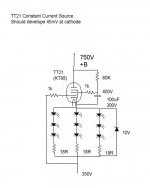
I'am now working away and trying to get a workable ccs parafeed version of the RH807SE, but have a problem, I just can't work out the current through the 807, so I can't design the current source. Anyone care to hazard a guess .
Running the TT21 at low enough currents to drive the 807 is proving challenging, its just not designed to go that low. Still should hopefully make for extended tube life. I'am going to base the CCS on Gary Pimms pentode current source design.
Shoog
I was just looking at a KT88 datasheet in order to try to work out how to get this current source to work. In Gary Pimms design it need at least a few mV of control grid current to get the circuit to work (in order to load the voltage reference IC). I can't see any operating point for which an anode voltage of 450V and any screen voltage gives any control grid current.
Heres a link to the current source
http://home.pacifier.com/~gpimm/el84_plate_load.gif
Any ideas ?
Shoog
Heres a link to the current source
http://home.pacifier.com/~gpimm/el84_plate_load.gif
Any ideas ?
Shoog
- Status
- Not open for further replies.
- Home
- Amplifiers
- Tubes / Valves
- Looking for KT88 circuits.