I got scammed from a craigslister. I have a rockford fosgate 400.4 that powers up (no protect light) but no audio output. I have one channel (rear left) thats moving my speaker without any input audio. The other outputs im getting nothing. I have some background with electronics but not much with car amps. I checked the mosfets. No shorts were found. Im getting a short between the 1 and 3 legs on the two diodes on the rail but im not sure if thats the problem. Anyone have a better idea of what I have going on or what I can check next? 😕
the short between 1 and 3 legs of diodes is normal, because are connected directly to the secondary winding of the transformer.
Perform this test:
With a voltmeter meter, position the black probe on the secondary ground, alternately position the red probe on the pin 2 (or metal body part) of each power diode.
You should see the dual power supply voltage.
Do the same for other service voltages that feed the preamplification stage.
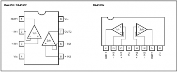
With the black probe always connected to the secondary ground, it measures the voltage on pins 4 and 8 of the operational amplifiers.
You should see 2 identical and opposite voltages (probably +/- 15v).
Post here the results.
Perform this test:
With a voltmeter meter, position the black probe on the secondary ground, alternately position the red probe on the pin 2 (or metal body part) of each power diode.
You should see the dual power supply voltage.
Do the same for other service voltages that feed the preamplification stage.
With the black probe always connected to the secondary ground, it measures the voltage on pins 4 and 8 of the operational amplifiers.
You should see 2 identical and opposite voltages (probably +/- 15v).
Post here the results.
I have 18.9v on one diode and -18.9 on the other when putting black lead on ground wire and red on pin 2 of the diodes. I'm unclear on what else to check. "Pins 4 and 8 of the operational amplifiers"???
What is particularly difficult?
I do not know what the dual power supply voltage of this amplifier should be, but it looks okay even if I expected a higher voltage.
NOTE:
The black multimeter probe must be connected to the secondary ground, not to the primary power supply (12v).
The secondary ground corresponds to the point where the rail capacitors join.
Now, to try to solve the problem, it would take at least one oscilloscope.
Inject a 50hz sinewave signal to the input of all 4 channel (set the crossover to full range).
With the probe, check pin 1 and 7 of all operational amplifier.
You must see the same signal but with different amplitude.
Oh, the shield of probe, must be connected to RCA ground.
With the probe, check pin 1 and 7 of all operational amplifier.
You must see the same signal but with different amplitude.
Oh, the shield of probe, must be connected to RCA ground.
Can anyone recommend o scope option on the cheap, I dont plan on fixing these things for a living. I see usb ones, diy kits, and phone apps. will any of these work for what im doing?
perfect.
Measures the voltage on the Q102 emitter.
If you read more than -11 volts (be careful, negative voltage), you have a problem with the muting / delay circuit.
If you read less than -9.5volt (be careful, negative voltage), let's go beyond finding the problem.
Measures the voltage on the Q102 emitter.
If you read more than -11 volts (be careful, negative voltage), you have a problem with the muting / delay circuit.
If you read less than -9.5volt (be careful, negative voltage), let's go beyond finding the problem.
Ok. I will let you know. I was using the main ground before because im not sure where the secondary ground is. Do you know where a spot I can use for the secondary ground test point?
Ok. I will let you know. I was using the main ground before because im not sure where the secondary ground is. Do you know where a spot I can use for the secondary ground test point?
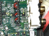
you can use the point marked with the red arrows as secondary ground.
Attachments
Maybe I'm just not seeing it but I see no q102. I'll keep looking but I did notice that I have -19.0 volts D.C. Coming out of my rear/left term output. (Black lead on negitive). All others no voltage. Does that clue help solve the mystery?
A good quality used analog scope (CRT display) is what I'd recommend for audio repair work. An app for your phone won't allow you to see DC on the circuit. Cheap scopes with LCD displays typically have very low resolution. Something like a BK Precision 2120 in good working order is a good choice and relatively inexpensive (watch shipping costs).
Last edited:
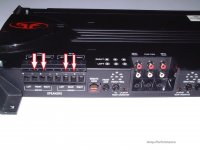
Is this your amp?Maybe I'm just not seeing it but I see no q102. I'll keep looking but I did notice that I have -19.0 volts D.C. Coming out of my rear/left term output. (Black lead on negitive). All others no voltage. Does that clue help solve the mystery?
http://images.crutchfieldonline.com/products/2004/575/x575P4004-f.jpeg
if yes, looks better, q102 is visible in the circuit area where the left front channel resides.
Also, if you really read -19v at the output of one of the 4 channels, then you will definitely have a problem with that channel, for example, shorted output FET ( do you know how to test them?) or FET drivers (related to Channel that pulls out continuous voltage).
If there is anything short, it is very strange that the amplifier does not present the protection.
Looks like this. Rockford Fosgate Punch P400-4 400 Watt 4-Channel Amplifier at Onlinecarstereo.com
I didn't have any shorts on the output fets. How do I check the drivers?
I didn't have any shorts on the output fets. How do I check the drivers?
- Status
- Not open for further replies.
- Home
- General Interest
- Car Audio
- Looking for help! rockford 400.4 No output