I have been rebuilding a Sound Valves M60 monoblock amp. The power supply needed quite a bit of work, and while I was at it I replaced many of the smaller electrolytics. In getting the amp working again I discovered an adjustment pot in the preamp section, but no instructions for how to set it properly. I'm attaching the schematic and the pot is P1(20K) on the 12AT7. In other amps like this there were identical value resistors used in the plate circuit and the cathode circuit. I could just adjust the pot so that the plate and cathode resistance values are identical - but it seems like they could have done this with fixed resistors in the design. So it seems like there is some other reason for this adjustment.
I have searched for info on the Sound Valves amps and how to adjust this pot, but can't locate anything.
I'd appreciate anyone who has experience with this particular amp or this type of amp to give me some insights on how to make this adjustment.
Thanks.
I have searched for info on the Sound Valves amps and how to adjust this pot, but can't locate anything.
I'd appreciate anyone who has experience with this particular amp or this type of amp to give me some insights on how to make this adjustment.
Thanks.
Attachments
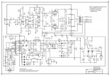
Is that P1 on the panel, or not? This schemo looks a lot like that of a guitar amp, and P1 would be another twiddle knob to deliberately unbalance the front end to add H2 to the output.
If it isn't, then I'd set P1 until its resistance matches the plate load (100K given here, but measure to be sure). Cathodynes don't require external balance like some phase splitter topologies, and so that thingie looks superfluous.
If it isn't, then I'd set P1 until its resistance matches the plate load (100K given here, but measure to be sure). Cathodynes don't require external balance like some phase splitter topologies, and so that thingie looks superfluous.
It looks like an AC balance control to get identical output amplitudes from both outputs of the concertina phase splitter. You might input a test signal, say 1kHz or so, and look for identical AC amplitudes at the plates of both driver stage plates, which would balance that stage as well as the splitter. Or you can look for a distortion minimum at the properly loaded speaker terminals if you have a distortion analyzer.
The Pot P1 is buried inside the case on the circuit board - so it's not readily accessible. There are adjustments (P2 and P3) that are user adjustable for setting the bias of the output tubes however.
It looks like an AC balance control to get identical output amplitudes from both outputs of the concertina phase splitter. You might input a test signal, say 1kHz or so, and look for identical AC amplitudes at the plates of both driver stage plates, which would balance that stage as well as the splitter. Or you can look for a distortion minimum at the properly loaded speaker terminals if you have a distortion analyzer.
I did come across some info that the setting of P1 had to do with minimizing distortion. Is there some way to get an approximate setting without a distortion analyzer - I don't have one of those in my collection of test equipment.
The desing is a bit strange. P1 is obviously for the AC-balance for whole amplifier, i.e. to compensate the gain difference of output tubes.
But the place of this adjustment is wrong, because the balanced voltage amplifier after phase splitter tends to compensate the phase difference at it's input.
If the total unbalance were for example 1 dB, the cathodyned should be adjusted to, say 3 dB unbalance. Better AC-balance adjustment would be to have one of the anode resistor of balanced amplifier adjustable.
Most people have distortion meter eventhough they do not know it.
Any laptop or PC with sound card together with one of those free or low priced audio programs form a good audio analyzer. Like this one: Latest News. Audio Rightmark
Yes, that is the wrong place for a phase-balance adjustment. And why would one be needed anyway - I thought guitar amps are supposed to have distortion?
Interestingly, there is a small capacitor (C6) which deliberately unbalances the PS at the cathode - unless it is compensating for wiring strays in the anode circuit.
Interestingly, there is a small capacitor (C6) which deliberately unbalances the PS at the cathode - unless it is compensating for wiring strays in the anode circuit.
Do you have an oscillator or other source of test tone and a DVM?
I do have an oscillator that I could use for a test as well as a Fluke multimeter. How would you suggest using them to make this adjustment?
I also have a Rigol scope with an FFT function that I thought might serve as a crude distortion meter.
My first thought was that I should adjust P1 so that I had equal gain at the plates of the 12AU7, or at the plates of the 6550 tubes. I wasn't sure if I could make any meaningful measurements at the output transformer since I don't have a distortion analyzer.
I haven't found any other Williamson type amps with the same sort of Pot adjustment at the inverter. If anyone has a detailed service manual for the Sound Valves monoblock that might have some info on this adjustment.
Any other thoughts would be appreciated.
Yes, that is the wrong place for a phase-balance adjustment. And why would one be needed anyway - I thought guitar amps are supposed to have distortion?
Interestingly, there is a small capacitor (C6) which deliberately unbalances the PS at the cathode - unless it is compensating for wiring strays in the anode circuit.
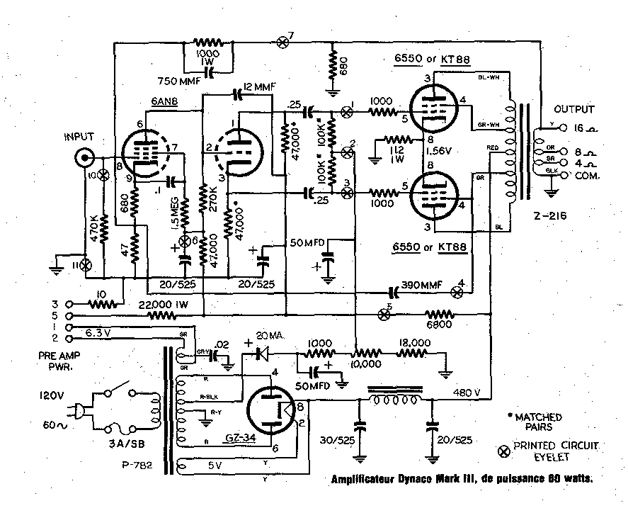
The amp is not a guitar amp, it's a hifi amp which seems to be derived from the old Dyna tube amps like the Mark III.
Not the wrong place and a very common practice in old amps (FISHER,SCOTT and many others). Adjusting one of the Concertina's phase splitter load resistors is the easiest way to AC (un)balance the circuit to minimize distorsion. The problem is that equal amplitude drive signal on the output tube grids doesn't necessary correspond to the lowest distorsion due to imbalances in the driver circuit, output tubes and transformer, and that's the reason of this adjustment. (otherwise they might have just used a pair of closely matched load resistors) The only way to adjust this properly requires a low distorsion signal generator and distorsion meter. There are alternate (less accurate) methods without a distorsion meter but you'll still need a (dual trace) scope and generator. If you don't have any of these test equipment just measure the (R8) plate resistor with a good DMM and adjust the pot to get exactly the same value from V3b cathode to ground.
If your output tubes are well matched you should be fairly close to minimum distorsion. Of course, this is a static adjustment and must be done with the amp disconnected and supply caps discharged.
If your output tubes are well matched you should be fairly close to minimum distorsion. Of course, this is a static adjustment and must be done with the amp disconnected and supply caps discharged.
Last edited:
In this amp any imbalance in the phase splitter is partly corrected by the driver stages due to their common cathode resistor (a short tail pair?). An adjustment in a driver anode would have more effect. Exact P-P balance only reduces even-order distortion and leaves odd-order unchanged. Perhaps chasing specs?
The driver works with higher currents and would need a higher dissipation adjustable pot, maybe this is the reason why the designers decided to use it in the phase splitter stage ?
Not the best option, but as a distorsion fine tuning it will work (more or less) as the driver imbalance compensation effect is only partial.
Not the best option, but as a distorsion fine tuning it will work (more or less) as the driver imbalance compensation effect is only partial.
The amp is not a guitar amp, it's a hifi amp which seems to be derived from the old Dyna tube amps like the Mark III.
This amplifier is more like Williamson design and essentially different than Dynaco MK3 (below). At Dynaco the phase splitter is directly driving the output tubes.
I am wondering why the high frequency response of Sound Valves M60 is "adjusted" at four different points. Is really necessary ?
With present component values the frequency response of the driver stages is some -6dB down at 20 kHz. This is certainly compensated by GNFB loop but is a sign of non-HIFI design.
Secondly, the overall THD at the 12AT7 / 12AU7 driver would be lower if the 12AU7 stage were eliminated and the lost gain compensated at the voltage amplifying stage.
Not necessarily. The frequency compensation is likely to be a consequence of high global NFB, which is a sign of hi-fi design. In many cases the crucial issue will be where the OPT HF resonance sits, because that determines how quickly the loop gain has to be reduced to maintain stability.artosalo said:With present component values the frequency response of the driver stages is some -6dB down at 20 kHz. This is certainly compensated by GNFB loop but is a sign of non-HIFI design.
I agree that very high GNFB seems to be used, because stability and/or frequency response problems have appeared.
Usually the characteristics of the OPT are not very demanding if the amount of GNFB stays below 12...14 dB. When required GNFB is above 20 dB, the case is completely different.
I see it so that when oversize GNFB is necessary, then optimum circuits or solutions are not used.
When all technical solutions are well designed the required GNFB is within above limits and still the THD and frequency response are very well.
In this case I suppose one of the main the reasons for the used high GNFB is the 12AU7 stage after phase splitter. It is very unlinear with shown component values.
The THD of the stage with required output level ( some 35 Vrms) is about 3 %.
As a reference, a well designed UL-ouput stage can deliver 90 % of the maximum output power with some 1 % of THD. And typically a cathodyne can deliver this voltage level with less than 0,5 % of THD.
And we can see what the final outcome is. Now high GNFB is used to have acceptable THD, but the average quality OPT has caused stability problems which have been solved by manipulating the open loop frequency response.
My opinion is that this is not professionally designed construction.
I believe the Mullard 5-10 used about 30dB of feedback. I guess you regard that as 'not professional' or 'not optimum'.
I do have an oscillator that I could use for a test as well as a Fluke multimeter. How would you suggest using them to make this adjustment?
I also have a Rigol scope with an FFT function that I thought might serve as a crude distortion meter.
My first thought was that I should adjust P1 so that I had equal gain at the plates of the 12AU7, or at the plates of the 6550 tubes. I wasn't sure if I could make any meaningful measurements at the output transformer since I don't have a distortion analyzer.
I haven't found any other Williamson type amps with the same sort of Pot adjustment at the inverter. If anyone has a detailed service manual for the Sound Valves monoblock that might have some info on this adjustment.
Any other thoughts would be appreciated.
Temporarily connect capacitors to the plates of the output tubes. Apply a sine wave to drive the amplifier to about 30% power. Measure the AC voltage at each plate to ground. The transformer action from each output tube will have a great affect on keeping the voltage the same, but the resistance of the transformer will allow small differences to be measured. Tweak the pot until there is no difference.
- Status
- Not open for further replies.
- Home
- Amplifiers
- Tubes / Valves
- Looking for expertise in adjusting Williamson amp