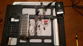
I recently ordered a kit to build JLH amplifier and worked on it over the weekend. I assembled the first channel on the pcb and had some trouble. I've done a bit of soldering, but not any on a board so it was a bit of a mess. I must have created a short somewhere, but I had trouble finding it. I decided to just put the other channel together without the board. It looks like a real mess, but sounds good so far. I am just using a wall wart I picked up at Goodwill as a power source for now. Anyway, I plan to take the components off of the board from the other channel and put it back together without the board. I attached a photo of the working channel.
Here's my question: Can anyone recommend a good resource where I could get some tips on planning and doing point to point construction?
Here's my question: Can anyone recommend a good resource where I could get some tips on planning and doing point to point construction?
Attachments
Last edited:
Look at pictures posted by others. Note that what you have there is not normal point-to-point wiring, but 'hanging in the air' wiring. It will probably be unreliable, as solder is not intended to provide strong mechanical joints. OK for a quick prototype, but not for something you intend to use. Almost all components should attach to something solid, like a tag strip or (in the olden days) valveholder etc.
One tip, if you received a commercial board in a kit, it needs to have the copper side cleaned before soldering. And use extra flux if necessary. That will reduce or eliminate solder not sticking well.
Usually, soldering to a PCB is pretty straightforward if (as Enzo said) the board is reasonably clean and I'm using good solder and a decent iron. A flux pen is a handy thing as well.I recently ordered a kit to build JLH amplifier and worked on it over the weekend. I assembled the first channel on the pcb and had some trouble. I've done a bit of soldering, but not any on a board so it was a bit of a mess.
What sort of soldering setup (solder, iron, tip, accessories like wick, flux pen, solder sucker, etc.) do you have ?
Some of the solder joints on your 'tacked together' 'prototype' could be better, I think.
P2P to good mechanical tie points works well for tube builds, but I find that a PCB is much more convenient for most solid state builds using small transistors and radial lead caps. So IMO don't give up on your boards unless you have wrecked them by lifting traces, etc..
Here's my question: Can anyone recommend a good resource where I could get some tips on planning and doing point to point construction?
Google has some and FWIW, when we designed/built custom panels we drew up a ladder diagram and the wiring personnel just 'connected the dots', so to speak. 😉
https://www.google.com/webhp?source...v=2&ie=UTF-8#q=point+to+point+wiring+tutorial
https://www.google.com/webhp?sourceid=chrome-instant&ion=1&espv=2&ie=UTF-8#q=ladder+diagram+basics
GM
Thanks for the advice everyone. I think I will try the pcb again. I need to clean the tip on my iron and perhaps get a better one.I had a heck of a time heating both the component lead and the metal on the pcb. I'll also pick up some better wire cutters and watch some videos.
I may try to build another one using point to point constuction because I like the idea of planning it and doing it myself.
Question: If both methods (using a pcb or point to point) are done well and use the same components, will there be any noticeable difference in sound quality? My guess would be no, but the point to point construction seems like it would be easier to repair or modify.
I have been caught out in the past with pcb's.
Especially none solder masked pcb's.
I built a Maplin amp and blew 3 transistors when I had a solder bridge across two tracks.
It was hard to find as some of the tracks were very close.
I find having two soldering iron tips of different sizes useful.
I have a small one for fine work (pcb's) and larger one for heavier work like jack sockets and connectors.
Look at the pcb as you go along for gaps in the tracks when you are soldering so you can tell when you have shorted something out.
You could use tag strip or strip board to make your circuits on as these support your components better.
These days I rarely prototype as you can pick up pcb's so cheaply in China.
I paid $10 for 10 pcb's plus $25 shipping.
www.pcbway.com are very good.
Last edited:
Success! Well, I think the main problem was an absurdly dirty tip on my iron. I picked up a new tip and a solder wick, and it went pretty well. I managed to break off a lead on one of the 3906 transistors. Of all the pnp transistors on my parts receiver, the closest match seemed to be an A1015. It seems to work, but I'll probably pick up another 3906 to use. I'm now waiting on my power supply kit and watching goodwill for a possible chassis.
An externally hosted image should be here but it was not working when we last tested it.
- Status
- Not open for further replies.
- Home
- Design & Build
- Construction Tips
- Looking for advice on point to point construction