Hello. I'm building the CNC phono stage, using the muffsy board (gerber files and pdf of the silkscreen are attached here). I'm looking for advice on the best way to add a mono switch to this phono pre. Any advice is appreciated!
Attachments
I'm looking for advice on the best way to add a mono switch to this phono pre.
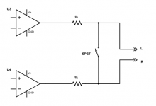
At each output, add a series 1k resistor. Then connect a SPST switch across the resistor outputs.
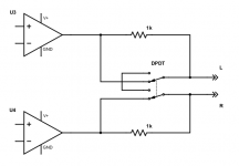
If you need tie points to mount the parts, use a DPDT switch instead.
Phono mono-1
Phono mono-2
Last edited:
At each output, add a series 1k resistor. Then connect a SPST switch across the resistor outputs.
If you need tie points to mount the parts, use a DPDT switch instead.
Thank you for the reply. I'm very new to DIY, so I'm not 100% sure what this should look like. Are you saying I should have the Left Out from the board and a 1k resistor soldered to the Left RCA out jack, and that the resistor should get wired to a SPST switch (and same with the right side with the resistor to the other terminal)?
Thank you for the reply. I'm very new to DIY, so I'm not 100% sure what this should look like. Are you saying I should have the Left Out from the board and a 1k resistor soldered to the Left RCA out jack, and that the resistor should get wired to a SPST switch (and same with the right side with the resistor to the other terminal)?
If the pcb outputs go directly to an output RCA jack, replace the wires each with a 1k resistor.
Mount the SPST switch between the RCA output jacks. Then wire the switch between the
hot terminals of the RCA output jacks, like in this diagram. Phono mono-1
If the wires are more than a couple of inches long, you'll need somewhere to mount the resistors,
so use the second diagram and you can mount the resistors on the switch terminals.
Mount the DPDT switch between the RCA output jacks, and mount the resistors on the switch,
like in this diagram. Phono mono-2
If you need a drawing instead, let me know.
Last edited:
..., like in this diagram. Phono mono-1....
Clever use of free drafting software. Also for collaboration.
But some members will balk at the "Login" and "Sign your design away, OK?" screens.
You can Export, get the PNG or PDF, and tack it into your message. (Also preserves your design for posterity.)
Attachments
If the pcb outputs go directly to an output RCA jack, replace the wires each with a 1k resistor.
Mount the SPST switch between the RCA output jacks. Then wire the switch between the
hot terminals of the RCA output jacks, like in this diagram. Phono mono-1
If the wires are more than a couple of inches long, you'll need somewhere to mount the resistors,
so use the second diagram and you can mount the resistors on the switch terminals.
Mount the DPDT switch between the RCA output jacks, and mount the resistors on the switch,
like in this diagram. Phono mono-2
If you need a drawing instead, let me know.
Thank you so much for taking the time to do that! I really appreciate your help. I'll be able to use the SPST switch per your first diagram.
Clever use of free drafting software. Also for collaboration. But some members will balk at the "Login"
and "Sign your design away, OK?" screens. You can Export, get the PNG or PDF, and tack it into
your message. (Also preserves your design for posterity.)
Usually I have to make enough revisions that the live link is more practical for me here.
Certainly I wouldn't recommend using a web site for confidential info, though many do.
Attachments
Last edited:
Completed the build. Thanks again Rayma!
Here's a photo of the completed build. It works beautifully, and the mono switch reduces the surface noise significantly. Thanks, Rayma, for your help!

Here's a photo of the completed build. It works beautifully, and the mono switch reduces the surface noise significantly. Thanks, Rayma, for your help!
At each output, add a series 1k resistor. Then connect a SPST switch across the resistor outputs.
If you need tie points to mount the parts, use a DPDT switch instead.
Phono mono-1
Phono mono-2
Here's a photo of the completed build. It works beautifully, and the mono switch
reduces the surface noise significantly.
Nice work.
- Status
- Not open for further replies.
- Home
- Source & Line
- Analogue Source
- Looking for advice on how to add mono switch to CNC/muffsy phono stage