Well, there is a lot that could be done.
I simulated the magnetic pickup circuit (using BC550C model transistors) and the two transistor design I have to say is quite disappointing, followed by a single tone control transistor, but I haven't simulated that. It looks high distortion and noise, not quality.
I used to think of Sony as being high quality for reasonable cost, but the more units I have dismantled (and now seeing the TA-70 circuit) convinces me that they were a Japanese "sinclair" - penny pinching to the last but with additional "marketing switches" for loudness and filtering options. You can see this in the number of shared resistors between the two channels. Channel separation?
Anyway, the RIAA response is somewhat inferior. The LF response has a massive cut-off due to low value input, output and in-circuit coupling/decoupling capacitors.
I haven't included the effects of the tone control but I suspect that will provide some additional HF roll-off.
You could improve the RIAA characteristics with optimised component values, (Sony picked near component values from the standard ranges) but a three-transistor circuit with a passive HF roll-off would be better still.
The tone control circuitry would be better with a three-transistor design too (input buffer to provide a source-independent drive impedance with a two transistor tone control) which properly balanced will give a proper flat response when the tone controls are set flat, and would use linear pots not the passive cut log pots in the Sony, which requires a high impedance output.
I'd drop the "loudness" and HF filter switches so that an ordinary volume pot can be used instead of the centre tapped unit.
With two transistor tone control you can get a larger signal output (typically x10) with low distortion which would allow the power amp gain to be reduced (with reduced distortion too). I'd probably add a balance control on the power amp section feedback (not elegant but provides perhaps a 2:1 to 1:2 gain ratio spread) or a simple linear pot ahead of the volume control.
Just to follow up on the power amp - the output transistors in the original are only 18W 40V 3A TO-66 transistors. They are being pushed to their limit (or just beyond) at 30W.
A complementary pair which would work would be the MJE3055T/2955T in TO-220 which can be made to fit the TO-66 hole pattern. These are 75W 60V "3055-ish" devices.
Driver transistors in the Sony are underpowered in my view, not dissimilar to BC547/BC557 but should be more like BC337-327 (up to 45V) or BD139/140 (up to +/-40V), and on the same heatsink as the output, and also the bias regulator which I note has fixed bias resistors but should be (ideally) adjustable. (Using large-ish emitter resistors with no adjustment is cheaper to build).
You could reduce the emitter resistors in the outputs to 0.47 or 0.33 with an adjusting pot.
It's an ideal upgrade project, which you could limit to simply optimising the existing circuitry or if the preamp is "supercharged" you could use the three transistor options I mentioned or even a decent audio IC which would save board space.
BD911/912 (Same as 2N6488 series) will make life much easier on the drivers than the TIP3055. They may very well use the same dies (same process for sure), but you won’t get one with a gain of 5 at 7 amps like you can with a 3055 on a bad day (I have measured this on MJ15015’s I’m not making this up). Should still upgrade drivers anyway - I never really liked the idea of using regular TO 92’s there unless the supply voltage is *really* low. If you have a stash of the old “giant TO-92’s” use them.
Quick preamp sims-
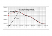
graph shows comparison of Sony as is (but without including the tone control, just taking the output from the RIAA mag stage), along with an optimised component value set with (a) 10uF output coupling capacitor (into original 1.5+5.6k load) and (b) 2.2uF. (but using BC550C transistor models - maybe original devices had lower gain).
Depending on which reference point you want to take the Sony response, the LF response is high for the mid band or the midband low compared with the optimise component values.
My guess that the rapid bass roll-off is to cut out rumble on a lower quality turntable and/or to match a cheaper loudspeaker system (that is, one with a limited bass response?). As Sony also sold speakers , I suspect the latter. Maybe wrong, but that is my impression.
Attachments
Last edited: