If you want parts that are common, you'll have to get with the times and build something with SMD transistors.
Smallest pins I've soldered were an STM32F103 chip by hand (admittedly a bit sketchy) but I'm quite comfortable with SOIC and passives down to 603. being able to "flick off" parts to try different values is pretty convenient actually.
Which means no perf boards, and no rolling your own etched boards. Get a board manufactured or you don’t build. THAT is the real limitation of SMD technology. You can’t just try something in an afternoon or weekend. I know it is getting CHEAPER, but *only* if you get them made in some country that many would not like to do business. Domestically, you’re still looking at a couple hundred bucks just to do something small and dirt simple. Which is why I have a huge stash (lifetime supply) of blank copper clad FR4 full panels I bought from Skycraft. The whole thing cost me less than one board run in the US.
Can still get the output transistors in thru hole, if you make use of the 6 types they offer, and a have an an NPN and a PNP of the same family in stock. I suspect you will always have TO-220 and flat packs for the SMPS market. But “in the end there can be only one” - at some point there will be exactly ONE TO-3P audio output pair left on the market, intended to replace ALL of what is currently being used. Along with an MJ15024 costing some thirty bucks (for the occasional desperate industrial user who can’t kluge a repair by company policy). It’s happening with TO126/TO-220 driver transistors now. Remember how many choices you used to have back in the 80’s and 90’s compared to today?
There is still enough stock (and surplus) out there, if you don’t need exotic or premium part. It is dwindling, and will eventually evaporate. 10 to 40 watt amps, even single digit ppm distortion ones, can be built using only jellybean parts. It’s only when you start upping the VOLTAGE that you can’t do that anymore.
Back in college I built a small amp running off a 25.2 VCT 2 amp Radio Shack transformer, using what amounts to a Blameless topology using ONLY 2N3904/3906 transistors and TIP41/42 outputs. It sounded every bit as good as my larger amps, when used at a background music level. The limitations of Radio Shack transistors is/was strictly the voltage. Even with the comparatively slim pickings at Mouser lately you can do *better* that that.
PCB fab OSHPark (formerly named DorkbotPDX) is in Portland Oregon and rather inexpensive. DigiKey's PCB service is based in Minneapolis but people claim they subcontract to overseas factories.
digikey usa still has leaded 2n5401 2n5551 in to92. Newark still has mje15028 and mje15029 . Get them while you can.
I had a good stock of all these leaded parts. Carried off by the burglar to the copper scrapyard 9/20.
I had a good stock of all these leaded parts. Carried off by the burglar to the copper scrapyard 9/20.
Tough times to be playing in the analog domain... I'm also into Synth DIY and there are many chips that community wishes were still around like OTAs, matched transistor packs, VCO/VCF/VCA-on a chip etc... Now we have to replace every OTA with the LM13700, make them out of discrete transistors, or wait for Behringer's Coolaudio fab to be our savior.
Seems like the rest of the industry has gone the way of code and PWM for eveything :'(
Seems like the rest of the industry has gone the way of code and PWM for eveything :'(
My unreliable crystal ball makes the following untrustworthy predictions:
>100V TO-92 transistors that will remain in production thru 2026: MPSA42 / MPSA92
>100V TO-126 transistors that will remain in production thru 2026: MJE340 / MJE350
>200V power transistors that will remain in production thru 2026: MJL3281, MJL1302
If you dropped these into a Blameless amplifier circuit, from D. Self's book "Designing Audio Power Amplifiers," you'd have a high quality amp built with COMMON parts.>100V TO-126 transistors that will remain in production thru 2026: MJE340 / MJE350
>200V power transistors that will remain in production thru 2026: MJL3281, MJL1302
My guess is that the A49/92 won’t survive except SMD, 340/350 I give 50/50, but the 3281/1302 is spot on. Although I believe it will be the NJW variant to be the last man standing. They can’t offer 3 package options forever, and it will be the cheapest that survives.
1) It is over 40 years old. I'm not a re-cap guy, but this one is due, especially with that complaint.
2) C705 C706 C805 C806 are half the values I would have used in a cheap amp in 1972. Especially with no NFB around the output caps. Today I would go 470uFd and 4,700uFd. Or as near as will fit (and caps are much smaller now). C303 double or triple.
Sony TA-70 Stereo Integrated Amplifier Manual | HiFi Engine
Ok so I fitted a 3300uF at C706/C806, now I'm getting some crazy woofer excursion when I turn the amp on. These I'm guessing are speaker coupling caps so I guess this happens because bigger value means it takes longer for these things to charge... I'm not sure I want to subject my speakers to this
What is the role of C705/C805 in the circuit? And why would I want to make these bigger?
Which means no perf boards, and no rolling your own etched boards. Get a board manufactured or you don’t build. THAT is the real limitation of SMD technology. You can’t just try something in an afternoon or weekend…
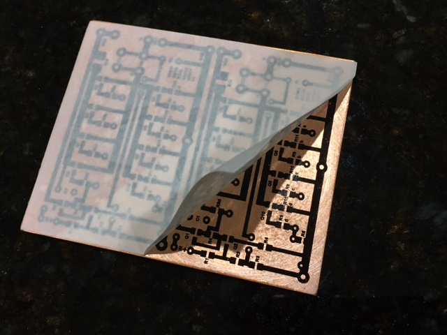
I actually think you can try out new SMD stuff much faster than through hole with home etched PCBs. They don’t require drilling which is a total pain as those tiny drill bits break if you look at them the wrong way. I think the parts are faster and easier to solder and no leads to trim.
I used to make my own home etched SMT PCBs all the time. Took about an hour.
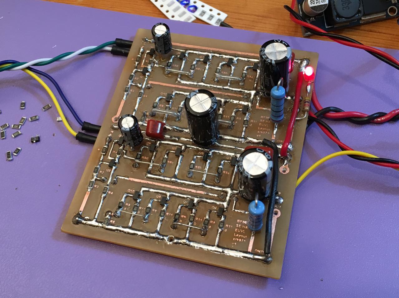
Here was a headphone amp I made quickly:
I made the artwork with the draw program in PowerPoint. Then used the laser printer toner iron o. process for the etch mask.
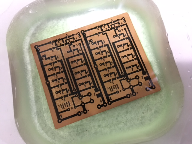
Acid bath:
Nowadays I am lazy and just wait a week for the boards to come back from
JLCPCB.
Tbh I think the part about fragile PCB drills is hogwash.
I've had the same set of 0.5mm to 1.2mm PCB bits for the last 12 years, and no breaks...
In fact, I just ordered a brand new set, as...well, after 12 years and hundreds of PCBs the bits are a little blunter than I like.
Though I should really try some SOT23, as there's one other package I like (for a guy that hates all SMD) and I think it's to252, because I can manipulate it to work on stripboard or TH PCB.
At least I think they're SOT23 packages. I can't solder the silly little TI ones
Last edited:
My Ax6-ST120 with 3300 uf of supply cap for both channels, doesn't thump at turn-on. It does have 3300 uf speaker cap for each speaker. Post #7.Ok so I fitted a 3300uF at C706/C806, now I'm getting some crazy woofer excursion when I turn the amp on. These I'm guessing are speaker coupling caps so I guess this happens because bigger value means it takes longer for these things to charge... I'm not sure I want to subject my speakers to this
I save no schematics on Sony products. However, single supply amps have a cap series the speaker. Some of them thump at turn-on. The plus, if you made a bad solder joint & it pops loose, it doesn't fry your speaker with 30 vdc. Other plus, 99% of DC protection boards sold for split supply amps have disconnect relays rated for AC, only. The contacts can weld together with a big DC surge through a shorted output transistor. The minus, lowest HD rating about .06%. Most speakers have higher HD than that.
Cheapest way to get 2 competent disconnect speaker relays is to buy a blown PA amp from a reputable company like Crown, Peavey, QSC, Yamaha that came with them. Then, personally, I rebuild them with tweaks to improve the sound if necessary. Like my M-2600 has a hissy TL074 op amp causing .2% HD. Can be swapped for MC33079 with added bypass capacitors or NE5533 with bigger +-15 v regulators.
Last edited:
The time constants of the input coupling, feedback, and speaker coupling need to be altered such that the DC at the output comes up more slowly. That will reduce the current during the charging cycle. Not a big deal with a small output cap which charges quickly, the excursion becomes smaller because it is effectively happening at a higher frequency. Won’t hurt anything, because the total energy required to charge a 3300 uF cap to 36 volts isn’t enough to eat even a 1/2” voice coil let alone a 1 or 1.5”, and a gentle single excursion to x-mech isn’t the end of the world either unless you’re using it for a dedicated tweeter amplifier. But a transient-free (or lowered magnitude) turn on is nice if you can arrange it, and in a bi-amp tweeter amp it’s mandatory. It is all in the sequencing - you just don’t want to switch the mid-Vcc operating point too abruptly. It is controlled by other time constants within the circuit and CAN be slowed down if you want to badly enough. The caution is that it may or may not help - because the behavior during charge and discharge are not necessarily symmetrical. Transistors which were not conducting at turn on ARE at turn off, so the resistances associated with charge and discharge are not the same. Quiet turn ON does not guarantee a quiet turn OFF. They do tend to be loosely related, though.
There IS a proper pole staggering for best clipping behavior of the amp at low frequency. It may or may not go against what is needed to keep the turn on/off thump under control. Typically, you want the low frequency cut off controlled by the INPUT coupling cap. This goes against minimizing distortion (an electrolytic WILL distort when at frequencies below where it acts as a dead short) so everything is a compromise. This is why input caps often get tripped out with film types.
There IS a proper pole staggering for best clipping behavior of the amp at low frequency. It may or may not go against what is needed to keep the turn on/off thump under control. Typically, you want the low frequency cut off controlled by the INPUT coupling cap. This goes against minimizing distortion (an electrolytic WILL distort when at frequencies below where it acts as a dead short) so everything is a compromise. This is why input caps often get tripped out with film types.
I know this is kind of besides the point and this is the sand forum, but when I think of a low wattage amp with common and repairable parts, I think of 12ax7s driving 6v6s, and either Hammond or Edcor transformers. Those parts are ubiquitous and affordable, both in new and harvested contexts
I think improving the built in amp is going down a rabbit hole that’s outside the scope of this project so i’ll leave the amp caps as is with original values; and continue my project of turning the second unit into a preamp. With that being said, would replacing electrolytics in the signal path within the preamp section with film types improve the sound? (I know I should *listen* to the final product before making these decisions, but I figure I should ask you these theoretical questions while I have you all here 🙂
Electrolytics act as capacitors through a nonlinear mechanism. The capacitance is thus voltage dependent. If the voltage is constant, or zero, you will never notice it. If the AC voltage developed across it is non zero, you will. This happens if it is behaving as a high pass filter at frequencies you can hear. Tends to distort the *low end*. Generally very low and for the most part inaudible, but it CAN be measured. The output cap on a power amp or tweeter series cap in a speaker crossover are the places where it is most noticeable. If the value is large enough where it’s impedance is negligible at 20 Hz, 2 Hz, or whatever, it falls below measurement threshold. In most pre amp applications, this is the case and the cap behaves close enough to ideal.
BUT electrolytics have a finite lifetime, often within the service life of the equipment. They dry out, lose capacitance, and develop additional series resistance. ESR increase is MOST pronounced when the cap has zero or very little DC bias. Coupling caps in split supply preamps, and all speaker crossover caps fall into this category and are at highest risk of this failure mode. When they go bad it isnt subtle - I’ve seen k ohms of ESR develop. That will cause a tweeter to just “quit”, or a feedback cap in an amp to cause a dramatic gain reduction. In places like that a film cap is desirable because that failure mode simply can’t happen, even if you weren’t worried about the .005% distortion a new electrolytic cap would offer.
BUT electrolytics have a finite lifetime, often within the service life of the equipment. They dry out, lose capacitance, and develop additional series resistance. ESR increase is MOST pronounced when the cap has zero or very little DC bias. Coupling caps in split supply preamps, and all speaker crossover caps fall into this category and are at highest risk of this failure mode. When they go bad it isnt subtle - I’ve seen k ohms of ESR develop. That will cause a tweeter to just “quit”, or a feedback cap in an amp to cause a dramatic gain reduction. In places like that a film cap is desirable because that failure mode simply can’t happen, even if you weren’t worried about the .005% distortion a new electrolytic cap would offer.
I know this is kind of besides the point and this is the sand forum, but when I think of a low wattage amp with common and repairable parts, I think of 12ax7s driving 6v6s, and either Hammond or Edcor transformers. Those parts are ubiquitous and affordable, both in new and harvested contexts
Quite true, but the entire 30 watt sand amp can be built for less than the cost of one Hammond or both Edcor output trafos.
Also, I would never suggest to anyone that a home brew tube amp be the very first thing they ever turn on. Learn safety and basic construction on something that can’t shock the bejeezus out of you FIRST. Even if it’s just a chip amp kit with an old car radio power amp IC and a 12 volt supply.
Tube amp building is like the dark side of the Force - once you embrace it you *will* forever be in its grasp, despite how many (and how big) sand amps you build. It is that addictive.
Electrolytics act as capacitors through a nonlinear mechanism. The capacitance is thus voltage dependent. If the voltage is constant, or zero, you will never notice it. If the AC voltage developed across it is non zero, you will. This happens if it is behaving as a high pass filter at frequencies you can hear. Tends to distort the *low end*. Generally very low and for the most part inaudible, but it CAN be measured. The output cap on a power amp or tweeter series cap in a speaker crossover are the places where it is most noticeable. If the value is large enough where it’s impedance is negligible at 20 Hz, 2 Hz, or whatever, it falls below measurement threshold. In most pre amp applications, this is the case and the cap behaves close enough to ideal.
BUT electrolytics have a finite lifetime, often within the service life of the equipment. They dry out, lose capacitance, and develop additional series resistance. ESR increase is MOST pronounced when the cap has zero or very little DC bias. Coupling caps in split supply preamps, and all speaker crossover caps fall into this category and are at highest risk of this failure mode. When they go bad it isnt subtle - I’ve seen k ohms of ESR develop. That will cause a tweeter to just “quit”, or a feedback cap in an amp to cause a dramatic gain reduction. In places like that a film cap is desirable because that failure mode simply can’t happen, even if you weren’t worried about the .005% distortion a new electrolytic cap would offer.
Thanks for this explanation! I guess this is why there are so many blown tweeters on cheap old speakers that have an electrolytic capacitor on the tweeter as a crossover.
I just recapped the entire thing from front to back so I think I’m good for a while. It’s a single supply preamp, but with a split supply balanced output stage salvaged from a mixer, so it has two separate power supplies.
The .06% HD reported of a Apex6 amp includes 3 electrolytic caps, the input, PS rail, and output caps. Less than the speaker distortion in 99.9% of speakers. At 1-70 watts I can't tell any difference in sound between it on my SP2-XT speakers and the .02% HD rated CS800s with no electrolytic caps in the sound path.Electrolytics act as capacitors through a nonlinear mechanism. The capacitance is thus voltage dependent. Generally very low and for the most part inaudible, but it CAN be measured. The output cap on a power amp or tweeter series cap in a speaker crossover are the places where it is most noticeable.
BUT electrolytics have a finite lifetime, often within the service life of the equipment. They dry out, lose capacitance, and develop additional series resistance. ESR increase is MOST pronounced when the cap has zero or very little DC bias. In places like that a film cap is desirable because that failure mode simply can’t happen, even if you weren’t worried about the .005% distortion a new electrolytic cap would offer.
I've found input & rail supply electrolytic caps wear out faster than the speaker cap in my 30 years with the ST120. Once in 30 years. Now we can buy service life rated caps, 3000 hours up.
Rail PS cap can be paralleled with a smaller film cap to improve high frequencies slightly. Peavey puts 2 uf film on the output transistor board of a 400 w/ch amp with 10000 uf rail caps 8" away.
BIggest expense of a home brew AX6 is the transformer. 44 v e core transformers have been available on e-bay in last 18 months. 2 amp & 7 amp varieties (Vermont transformer). My St120 amp has a 6.25 A capable dynaco transformer. My ST120 is 72 v, regulated to 70 v by 72 v zener & 5 parallel pnp darlington transistors with .33 emitter resistors, into the rail cap.
In a dual winding antekinc toroid transformer, you'd want a 30 v 700 va model. Two 30 v windings make 60 v. The high rail voltage, 70 , allows for the 70 W 5 second peaks I get out of the built AX6 channel. Also the surviving ST120 PC15 channel.
I listen at 1/4 W base level, but if the cannon goes off in 1812 Overture, it is nice to have 70 watts for a 72 db peak from a CD. SP2-XT are 101 db 1W1M. 95 db or 90 db speakers will require more power.
Most inexpensive enclosure is a metal file box or ammo can with a metal mesh top for cooling. Power amp sits behind the organ anyway, not visible. Heat sinks can be put outside the enclosure if a dog or baby won't touch the 70 v cases of TO3 transistors.
Gerber files for AX6 are in the earlier posts, also latest ones by prasi. Prasi has a builder of pcb in India if you ask him. He sent me some but he is not in business.
Happy shopping & building.
Last edited:
Thanks for this explanation! I guess this is why there are so many blown tweeters on cheap old speakers that have an electrolytic capacitor on the tweeter as a crossover.
Some of it. Sometimes it is the cap that goes bad. Last year I restored an old console stereo, and a bunch of electrolytics were bad, including the caps in the crossover. Resistance went high in those, resulting in tweeters not making much sound. The biggest problem was a blown TO-92 PNP darlington driver transistor (unobtainium, so I had to get creative). The filter cap was weak so it and a couple others got tripped out, too.
The other reason tweeters fail with just an electrolytic cap for a crossover is that it’s just insufficient high pass filtering (even if new) and it’s too easy to over power the tweeter and burn it out. Film caps don’t help here - a first order crossover in general isn’t enough. Not a problem when the biggest amps were those 10-15 watt amps in old console stereos, or with a pair of 6BQ5’s that can’t muster much more. But modern receivers can produce more - even the cheap modern stuff - and speakers developed for 10 watt amps won’t take it.
- Home
- Amplifiers
- Solid State
- Looking for a Low wattage, high quality, amp to build with COMMON parts