Hi there guys,
I'm looking for the schematic of the KEF Q550 crossover circuit. I am working on the amplifier which had the left channel blown which is used with the speaker. I am waiting for the spares to arrive. Until then I am trying to cross out all the possibilities which might have caused the fault.
Speaker driver being shorted out is one possibility as I have read. I am unable to measure this directly across the speaker terminals because I believe there is a capacitor in series and on the ohms meter I read values just like a capacitor charging.
Maybe a driver is open, resulting an impedance mismatch causing the left channel of the amp to blow? Could this be a possibility?
I haven't got access to the speakers at the moment and I would like to have a look at the schematic to make sure that in fact I wouldn't measure a driver being open or shorted out with the crossover circuit before opening up the speaker.
Thanks in advance for the help.
Not likely to be the speaker's fault. Could the speaker wires have been shorted
either behind the speaker, or at the amplifier?
either behind the speaker, or at the amplifier?
I measured at the amp - removed the speaker cable from the amp and put my leads on the cable.Not likely to be the speaker's fault. Could the speaker wires have been shorted
either behind the speaker, or at the amplifier?
Hypothetically speaking - what would I have measured if a driver was shorted with the crossover circuit in place? Would I be able to tell if a driver is shorted or open?
Now I measuring something like 0.7Mohms (the value climbs up and settles at 0.7Mohms). Both the left and right are showing the same values.
Sounds like one of the KEF crossovers that has a series capacitor, so it's an open circuit at DC.
If you have a signal generator, connect it to the speaker system through a 1k resistor.
No amplifier is needed, since the generator will make enough sound for testing all by itself.
Do all of the drivers make sound? If so, the speaker is probably ok. At any rate, an open circuit
cannot harm the amplifier. With the series capacitor, even a short in the crossover likely would
not harm the amplifier either.
Last edited:
Sounds like one of the KEF crossovers that has a series capacitor, so it's an open circuit at DC.
If you have a signal generator, connect it to the speaker system through a 1k resistor.
No amplifier is needed, the generator will make enough sound all by itself.
Do all the drivers make sound?
Thanks for the tip, I shall try that next time I am over there. Can I ask what's the purpose of the 1K resistor (current limit for possible short)?
Do you by any chance have a schematic for a similar kind of crossover, I have tried googling but haven't come across to something similar.
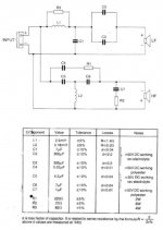
The 1k series resistor mainly protects the signal generator, but it could be as low as the rated generator impedance,
which is usually either 50R or 600R. Make sure that the resistor is connected in series with the speaker, not in parallel.
Here is a KEF 103 crossover to show the idea. Note that there is no DC path through the crossover.
which is usually either 50R or 600R. Make sure that the resistor is connected in series with the speaker, not in parallel.
Here is a KEF 103 crossover to show the idea. Note that there is no DC path through the crossover.
Attachments
Last edited:
The 1k series resistor mainly protects the signal generator, but it could be as low as the rated generator impedance,
which is usually either 50R or 600R. Make sure that the resistor is connected in series with the speaker, not in parallel.
Here is a KEF 103 crossover to show the idea. Note that there is no DC path through the crossover.
Thanks very much
- Home
- Loudspeakers
- Full Range
- Looking for a KEF Q550 crossover schematic.