> the cathode resistor (5600 Ω)
I *think* you meant to grab 333 Ohms (from step 7). You seem to have grabbed the plate load.
> cathode bypass capacitor ...low frequency cutoff. I like 5 Hz.
> Using "Z = 1/(2π FC)" set Z equal to the cathode resistor (5600 Ω), F = 5 Hz
> 5600 = ½ π 5 C
Strictly, you want to bypass Re||(1/Gm), the tube's internal cathode impedance.
merlin has picked a current right off the datasheet. Gm also depends on plate voltage, so we have a choice of 3,000uMho or 2,600uMho. 333 Ohms or 385 Ohms.
Take the lower value (bigger cap).
So far we have 333||333 or like (sliderule) 160 Ohms. At 5Hz this is 193uFd.
Caps vary 20%. Tubes vary 20%. If we MUST hit -3dB @ 5Hz, we better allow another 40%. 270uFd.
Strictly we should factor-in the plate load 5,600 divided by Mu. 5600/20 is 280 more Ohms which appears in series with internal cathode impedance 1/Gm.
333||(333+280)= 215 Ohms. Compare to 160 Ohms neglecting Rl/Mu.
Rules-O-Thumb:
1/Gm will be very similar to Rk in most practical designs. (Small triode at 9mA is pushing the limits and should be checked.) So it is expedient to compute on HALF of Rk to pick Ck.
Rl/Mu is generally a small correction, and is "conservative" (results will be better than computed) so this is often neglected.
I actually plotted the picture. Agree that ~~5K Rl makes more sense than my extreme bad-examples. 1.5K has low gain. 17K has no swing. ~~7K is a split-difference. I have used larger swings than 50V up, but that works fine also.
NICE WORK.
It is slide-rule easy.
GoatGuy
@artosalo
I have problems with my tx to reach B+ 300VDC 18mA, how can be changed the schematic for less B+ reaching the 18mA?
TIA
Felipe
I have problems with my tx to reach B+ 300VDC 18mA, how can be changed the schematic for less B+ reaching the 18mA?
TIA
Felipe
It seems my transformer can be enough for B+ 300VDC 18mA
No.I'm doing well the simulation for the psu?
With just a 1R resistor you won't have much filtering.
Last edited:
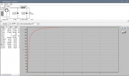
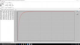
Do you know how easy it is to try something yourself in PSUD?
Just type in a different value and see for yourself how you arrive at the 300V or whatever you need.
Or change the topology. Replace the choke with a resistor... and what do you get?
Please sit down and try for yourself instead of constantly asking people for the easiest things.
Just type in a different value and see for yourself how you arrive at the 300V or whatever you need.
Or change the topology. Replace the choke with a resistor... and what do you get?
Please sit down and try for yourself instead of constantly asking people for the easiest things.
Please sit down and try for yourself instead of constantly asking people for the easiest things. 😉
> problems with my tx to reach B+ 300VDC 18mA
Tubes are NOT fussy. It will work about the same with 280V.
If you do not have a choke, try 100uFd 1K 100uFd. The 1K drops 18V but gives a LOT more buzz-filtering than lower values. Still for a line-amp I suspect you want a 3-stage filter: 100u-500r-100u-500r-100u.
Tubes are NOT fussy. It will work about the same with 280V.
If you do not have a choke, try 100uFd 1K 100uFd. The 1K drops 18V but gives a LOT more buzz-filtering than lower values. Still for a line-amp I suspect you want a 3-stage filter: 100u-500r-100u-500r-100u.
How much supply voltage do you have available ?
Here is one example:
What's the output impedance?
Attachments
![WP_20161126_002[1].jpg](/community/data/attachments/523/523070-13d8dc966ffc46045d1edb955a339f60.jpg?hash=E9jclm_8Rg)
What's the output impedance?
About 7kΩ.
I will use DC heaters is the same pin1 positive and pin8 ground or v.v.?
No difference.
How can lower the output impedance and increase the gain?
A cathode bypass cap would do both of these things.
- Status
- Not open for further replies.
- Home
- Amplifiers
- Tubes / Valves
- Looking for 7N7 preamp schematic