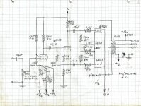
Here is Roddams cct 1(b) in hdwr. A simple PP 6AQ5 amp, circa 1956.
I used a short length of resistance wire to sample the current in the speaker leads.
By varying the pickoff point on the resistance wire it was possible to gradually
lower the loudspeaker resonant peak to the point where it was inverted.
Then stability set on pretty quick. For the finished amp only a short piece of
resistance wire was left.
This amp went to a friend who in his other life piloted an ME 109 for the other side.
Attachments
I notice you also have the -HFfb, like Dynaco used in their ST-35 with C6. I guess this is a stability tweek. Or maybe this is intended to reduce global N-Fdbk at HF by lowering gain. A crossover to local N Fdbk. Would there be any advantage in using a larger C6 here, with a series R, to set a definite break frequency?
Dynaco:
 ST-35.
Dynaco:
The OPTs in those daze (1955) for the most part were for use as replacements or in Public Address systems.
Most of them never saw any kind of NFB at all. So when it came to using NFB, we had to step carefully.
For the PP amps that meant a realistic limit of about 10 db NFB. I liked to be safe so about 7 db NFB.
I found that it was possible to damp the HF oscillation sometimes seen as a sine wave approached clipping.
Crowhurst covered this, I'll have a look in the AM, think I have that here in the pile.
About the same time I was doing these simple amps I found that the stray capacity of the ends of the
primary windings to the core were different, as much as 200 pF. That is an eye opener, don't think
we would find that on an OPT meant for FB today. But for the version of Crowhurst's Twin Coupled Amp
I built that factor had to be accounted for. It used a pair of universal OPT's. All covered in the write up.
The Hammond 1600 Series are much better today.
For a simple FB pair type amp I've used up to 20 db NFB with no problems at all. Even when the OPT
was in an All American Five (AA5) BC Receiver. In those I pulled the rectifier & replaced it with a SS diode.
Stuffed a 12J5 into the rewired 35Z5 socket. And replaced the 35L6 with a 50L6. so a FB pair
with 20 db NFB is possible. Then a terminal strip on the back to drive a 12 inch speaker in a ported box.
But its still AM!
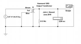
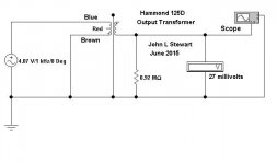
Test for parasitic capacity between primary leads & core, Hammond 125D.
For a SE OPT the red lead usually goes to the B+.
That way the plate of the power amp is not diving a large capacity.
Probably corrected in $$$ OPTs. But perhaps not, have a look.
The odd 0.91M load resistor in the schematic is a One M load in parallel with the 10M scope probe.
For a SE OPT the red lead usually goes to the B+.
That way the plate of the power amp is not diving a large capacity.
Probably corrected in $$$ OPTs. But perhaps not, have a look.
The odd 0.91M load resistor in the schematic is a One M load in parallel with the 10M scope probe.