Hi everyone,
I'm planning on building a Distortion Analyser adaptor for my two Oscilloscopes, using a design from an article I found online, the circuit of the Distortion Analyser looks relatively easy to build, and uses fairly common NPN bipolar junction transistors, should be a fun and useful test gear build project, I'll post a pic of the schematic later on.
I'm planning on building a Distortion Analyser adaptor for my two Oscilloscopes, using a design from an article I found online, the circuit of the Distortion Analyser looks relatively easy to build, and uses fairly common NPN bipolar junction transistors, should be a fun and useful test gear build project, I'll post a pic of the schematic later on.
Forget any old analog solution (and I am an old analog engineer with +40 years of experience); today all what you need is an USB interface and a PC/Laptop. with free software.
The leader of audio test instruments Audio Precision had "hardware analyzer" before; but many years ago they switched to digital analysis where the front end (their expensive analyzers) are just acquisition hardware and all the analysis is performed in the host PC.
This will be an easier and cheaper solution to implement, anyway keep a good analog oscilloscope to watch for small details lost in the digitalization 🙂.
Here we go, as promised, here is the schematic for the Distortion Analyser I'm planning on building as an adaptor for my Oscilloscopes, of course, I could have gone with a software solution, but I was really after a quick-and-dirty easy to build solution, besides, I enjoy building diy test gear anyway.

The whole idea is to build a Distortion Analyser adaptor for my oscilloscopes to give me some kind of visual indication when I do bias adjustments on amplifiers I build, I'm not really interested in something that's going to give me a highly detailed display of an amp's distortion harmonics, it's really just a rough and ready, quick and dirty display, it doesn't have to be overly complicated.
It is based on the idea of feeding a clean 1kHz Sine wave signal into the amplifier under test, then notching out the amplified 1kHz Sine wave signal on the output, what you have left after that is all the distortion harmonics produced by the amplifier which you can display as a signal trace on an oscilloscope.
And here's a link you can click on to download a pdf of the full article:
https://www.kennethkuhn.com/electronics/distortion_analyzer.pdf
https://www.kennethkuhn.com/electronics/distortion_analyzer.pdf
Well, it looks like you know what you really want, so go ahead with it.
The schematics you posted will give you a tool to do it; but keep in mind this will be THD at a single frequency, it is a well known double T notch circuit and you will not find a simpler circuit to do it.
The schematics you posted will give you a tool to do it; but keep in mind this will be THD at a single frequency, it is a well known double T notch circuit and you will not find a simpler circuit to do it.
The trouble with that circuit is that the twin-T notch filter can have its own distortion. That might swamp the distortion of the circuit you're trying to test.
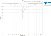
You could consider making the notch filter with a modern opamp. That can be quite low distortion. I've attached the response of one that I used a while back when I was trying to squeeze more performance out of the APx525 I used to have. The first measurement is with a passive twin-T notch filter. The second is the active filter. I might have a schematic of that floating around should you be interested.
Personally I would get a sound card and just measure the THD.
Tom
Attachments
Actually, this could be your ticket: https://www.diyaudio.com/community/...nterface-soundrite-2i2-usb-mic-preamp.416209/
Great combination.
Tom
Great combination.
Tom
- Home
- Design & Build
- Equipment & Tools
- Looking at building an easy to build Distortion Analyser adaptor for my Oscilloscopes.
