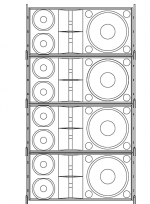
i'll be honest, i don't know much more then the basics. i came up with this from reading and looking at other designs. i have no idea what potential problems could arise if this system was operating. the subs are Xco1s T18. the tops consist of 12s spaced at 13.84" giving a crossover freq. of 490hz, the 2-6.5s are spaced 6.91" giving a crossover freg. rougly 1000hz, and 2-1" comp. drivers. from what i read a 1" comp doesn't like to go much lower then 1500hz, so i figure that is an issue. i have the 1" comps dispersing at 90 degrees horiz. and 10 degrees vert. i think. no magic with the waveguide and probably completely wrong, but i'd be willing to build and try. the box is just over 3 cuft. once again, i know the basics and i am an experienced cad operator. so, i get bored and try to figure things out.
Attachments
Nice looking drawing.i'll be honest, i don't know much more then the basics. i came up with this from reading and looking at other designs. i have no idea what potential problems could arise if this system was operating.
I told you the problems with this type of design in “Tops to accommodate Xoc1's T18” thread, here goes again 🙄.
The height of your "idea" line is quite short, only providing vertical pattern control to around 250 Hz.
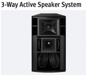
A couple “point and shoot” horn cabinets could do better, and cost far less in components and rigging hardware, an example of such type of cabinet below.
The narrow horizontal coverage of such a cabinet allows for side by side placement without comb filtering.
The center to center spacing between the 6.6” mids and highs in your design appears around 8.5”, to be within 1/4 wavelength (to avoid horizontal off axis comb filtering) would require a 400 Hz crossover, way too low for 1” drivers at high volume.
The center to center distance between the 6.5” and the 12” appears around 20”, to be within 1/4 wavelength (to avoid horizontal off off axis comb filtering) would require a 170 Hz crossover, the 12” would only be covering about an octave.
The lower HF horns and mids would be starting at only about 44” if the stack is ground supported, they will tear the heads off anyone in line, and the energy absorbed by said heads will not be available for those who need it at some distance behind them😱.
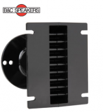
Standard HF horns don’t work well in line arrays, horns designed with very narrow vertical dispersion should be used, a B&C B&C ME102 1" waveguide coupler providing such is shown below, waveguides for the desired dispersion angle can easily be made.
That said, the ME102 relies on diffraction for horizontal dispersion, not as good sounding as conical horns...
If you are sold on a four way vertical array, a 4 x12” or 2x15” low mid box would provide elevation for the mids and highs, and a pair of 4 x 6.5” line boxes could be made.
A multiple driver waveguide using the ME102 would only need 4.4” of vertical height per driver. Six drivers would be adequate, and could be split in to three boxes, or one articulated cabinet allowing for three zone coverage, simple switch attenuators could reduce the short throw level by various amounts, still allowing a single amp side operation.
The HF could be placed in an MTM arrangement, or at the top of the line for longer throws.
A pair of 3x10”, or 3x12” boxes with the HF center or on top would work well, and reduce the complexity and cabinet count and allow 3 way operation, reducing amp count and crossover complexity.
Of course, you didn’t take any of the above suggestions in the “Tops to accommodate Xoc1's T18” thread before drawing your "idea", so I don’t know why I bothered repeating myself 😉..
Art Welter
Attachments
Nice looking drawing.
I told you the problems with this type of design in “Tops to accommodate Xoc1's T18” thread, here goes again 🙄.
The height of your "idea" line is quite short, only providing vertical pattern control to around 250 Hz.
A couple “point and shoot” horn cabinets could do better, and cost far less in components and rigging hardware, an example of such type of cabinet below.
The narrow horizontal coverage of such a cabinet allows for side by side placement without comb filtering.
The center to center spacing between the 6.6” mids and highs in your design appears around 8.5”, to be within 1/4 wavelength (to avoid horizontal off axis comb filtering) would require a 400 Hz crossover, way too low for 1” drivers at high volume.
The center to center distance between the 6.5” and the 12” appears around 20”, to be within 1/4 wavelength (to avoid horizontal off off axis comb filtering) would require a 170 Hz crossover, the 12” would only be covering about an octave.
The lower HF horns and mids would be starting at only about 44” if the stack is ground supported, they will tear the heads off anyone in line, and the energy absorbed by said heads will not be available for those who need it at some distance behind them😱.
Standard HF horns don’t work well in line arrays, horns designed with very narrow vertical dispersion should be used, a B&C B&C ME102 1" waveguide coupler providing such is shown below, waveguides for the desired dispersion angle can easily be made.
That said, the ME102 relies on diffraction for horizontal dispersion, not as good sounding as conical horns...
If you are sold on a four way vertical array, a 4 x12” or 2x15” low mid box would provide elevation for the mids and highs, and a pair of 4 x 6.5” line boxes could be made.
A multiple driver waveguide using the ME102 would only need 4.4” of vertical height per driver. Six drivers would be adequate, and could be split in to three boxes, or one articulated cabinet allowing for three zone coverage, simple switch attenuators could reduce the short throw level by various amounts, still allowing a single amp side operation.
The HF could be placed in an MTM arrangement, or at the top of the line for longer throws.
A pair of 3x10”, or 3x12” boxes with the HF center or on top would work well, and reduce the complexity and cabinet count and allow 3 way operation, reducing amp count and crossover complexity.
Of course, you didn’t take any of the above suggestions in the “Tops to accommodate Xoc1's T18” thread before drawing your "idea", so I don’t know why I bothered repeating myself 😉..
Art Welter
thanks Art. in this thread i wasn't looking for a design suggestion, i just wanted to know exactly why something like this would or wouldn't work; and you answered it for me. i'm trying to get an understanding to how frequencies work (educate myself). i have been reading this Phase, Time and Distortion in Loudspeakers. seems the only way to learn is to ask, read, and then experiment.
i've already decided to try my hand on a 2-12" + 1.4" or 2" comp. i do have questions about spacing for the drivers on the baffle, wasn't sure just exactly how critical this was.
- Status
- Not open for further replies.