Hi,
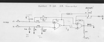
attached you find the output stage from my Perpetual Technologies P3-A with crystal CS 4396 DA convertor (voltage output, balanced).
Besides trying to understand this (especially the second opamp) I would like to convert this to something with a passive filter, x-bosoz with ccs (like Henrik showed in another thread) and keep everything balanced.
Just for fun I was looking what filter frequencies are in this standard output and here´s where the problem starts.
If I look at the first low-pass (1k, 5n6//1k) I ´m already 2.6dB down at 20.000Hz, The second stage (499R, 1n5) ads another 0,7dB to this so I´m down over 3dB at 20000Hz. Since this certainly isn´t the case I must be making a mistake somewhere in this (very simple) calculation
Can somebody point out what I am doing wrong?
Here´s the calculation:
z@20000Hz = 1/(2PifC) = 1/2pi*20000*5.6*10^-9 = 1421 ohm
1421//1000 = 587 ohm
587/(1000+587) = 0,3699
20Log0,3699 = -8,64dB (attenuation by cap + halving by second 1k)
8,64 + 6 = -2,64 dB
William
Attachments
Well the first mistake I can see is your first lowpass filter.
The loop impedance seen by the bottom 5.6nF capacaitor to
ground is 1k||Ik i.e. 500R assuming zero sourse impedance.
🙂 sreten.
The loop impedance seen by the bottom 5.6nF capacaitor to
ground is 1k||Ik i.e. 500R assuming zero sourse impedance.
🙂 sreten.
Well the first mistake I can see is your first lowpass filter.
The loop impedance seen by the bottom 5.6nF capacitor to
ground is 1k||1k i.e. 500R assuming zero source impedance.
Plug it into a circuit simulator.
🙂 sreten.
The loop impedance seen by the bottom 5.6nF capacitor to
ground is 1k||1k i.e. 500R assuming zero source impedance.
Plug it into a circuit simulator.
🙂 sreten.
sreten,
could you explain a bit more or do a calculation so I can see where I went wrong/how it is done? (I also assumed 0 ohm output impedance, otherwise the attenuation would be even bigger)
Circuit simulations are nice but don´t really help to understand how things work🙂
william
could you explain a bit more or do a calculation so I can see where I went wrong/how it is done? (I also assumed 0 ohm output impedance, otherwise the attenuation would be even bigger)
Circuit simulations are nice but don´t really help to understand how things work🙂
william
- Status
- Not open for further replies.