I'm trying to understand how long these tail pair + VAS on the attached screenshot work together and got 2 questions so far:
1. Why one of the differential output signals is picked up from a CCS (the emitter of Q5225) instead of the collector of the 2nd transistor of the long tail pair (collector of Q5125)?
2. Why there's no resistor between the power supply rail and the collector of Q5125 similar to R5105? Doesn't it break the symmetry of the whole long tail pair?
Attachments
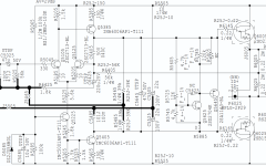

You're right, thank you!The resistor in the unused collector of the diff pair SHOULD be omitted. It’s a mistake to include it.
What could be some reasons for doing so vs introducing a complete and independent 2nd CCS? Just to save on a few components? Are there any known advantages\drawbacks between the two options?Q5405 IS a CCS. Not a signal amplifier. It’s base reference comes from a tap in the degeneration resistor for the LTP’s CCS