It's tough to debug this stuff from remote, especially when I haven't built the amp in question.
Did you have a read through the link I posted?
Is the 100W bulb staying lit brightly with the amp board plugged in? Or just a little dim?
If it's bright, you definately have a problem on the amp board somewhere. It sounds as though this is the case as well, being that your chip is getting hot. I would not expect any significant heat from these chips with no audio ground through them.
You say your rail-to-rail voltage is 58VDC? That seems reasonable.
But if your chip is getting hot, you have a problem. That's another sign that your amp board is pulling WAY too much current (a brightly lit 100W bulb being the other).
I can't help but wonder if your amp isn't oscillating. What's hooked up to its inputs? Are the right caps installed in the right orientation? Are your running the input wires right next to the output wires? What happens if you ground the input signals?
Check, double check your work. Check all of your solder connections visually and with the ohmmeter. Make sure nothing is installed backwards. This stuff takes a lot of patience and clear mind.
But don't run the chip hot for two long, or you'll fry another board. BTW, what exactly happened with the first ones?
Wes
I still say that the wires from the rectifier board to the amp boards may be reversed.
That seems to be the problem.

That seems to be the problem.
carlosfm said:I still say that the wires from the rectifier board to the amp boards may be reversed.
That seems to be the problem.
the rectifier board isn't hooked up backwards.... it's less than 1/2 inch from the amp board and the connections are dead on!
I'm taking pics now.... with the bulb on and such
oscillating seems possible... but how would I fix this
I'm reading 37vdc from the rectifier... both the V- to PGND- and V+ to RGND+ read this exact voltage
the chip stays quite luke warm.... the sink gets... probably slightly above room temp here...
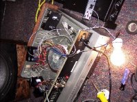
the pic at the very bottom shows how bright the 100w bulb is
I unfortunately don't have my good camera here... so you'll have to excurse the crappy pics... I couldn't get incredibly close... if you need me to I can take it outside so the flash won't do this ****
but I assure you... all the solder joints are COMPLETELY seperated.... I've looked it over 10+ times
but I assure you... all the solder joints are COMPLETELY seperated.... I've looked it over 10+ times
Attachments
wes-ninja250 said:I
I can't help but wonder if your amp isn't oscillating. What's hooked up to its inputs? Are the right caps installed in the right orientation? Are your running the input wires right next to the output wires? What happens if you ground the input signals?
nothing is hooked up to the inputs
they are just sitting off to the side not even attached to the RCA jack
the caps are 100% in the right orientation... EXACTLY how they look on the www.chipamp.com site for this board....
the input and outputs are a couple feet away from each other and neither are hooked up to the terminals
ground the input?
there isn't an input signal right now
this couldn't be caused by the board being so close to the xfrmer could it?
alright...
I hooked up the outputs to the jacks
and the inputs to the RCA jack
now the bulb BUZZES when I turn it on
I hooked up input to the amplifier... I can hear the damn music from SOMEWHERE IN THE AMP....
it's obviously very bad sounding... but I can hear a beat... the bulb also made this terrible WHINING sound...
wow
something seems really really screwed up
at the output jacks though... I'm not reading any output when the RCA jack isn't getting signal
edit: Ok now it's not buzzing and with signal I'm reading a fluctuating voltage on the AC scale from the outputs... music?
it goes between two and 3 v AC with the 100w bulb in line
the buzzing seems to be coming from the transformer....
I have an extra exact copy of this xfrmer... should I swap it out?
I have an extra exact copy of this xfrmer... should I swap it out?
Audiophilenoob said:the buzzing seems to be coming from the transformer....
I have an extra exact copy of this xfrmer... should I swap it out?
You are killing the transformer because you have a short or a reversed PSU wire to the amp or a reversed diode on the rectifier board.
The trafo will finally give up the ghost unless you use a correct fuse for it, in which case it would have blown 100 times but it would protect your trafo.
i would have to say yes to a shorted rectifier diode.
been there done that😀
and yes u will kill the transformer if you leave it on
been there done that😀
and yes u will kill the transformer if you leave it on
carlosfm said:
You are killing the transformer because you have a short or a reversed PSU wire to the amp or a reversed diode on the rectifier board.
The trafo will finally give up the ghost unless you use a correct fuse for it, in which case it would have blown 100 times but it would protect your trafo.
there is a 3amp fuse in line with the hot lead... hasn't blown yet
how can there be a shorted diode when the rectifier works GREAT without being hooked up to the board??
there is no reveresed wire... I swear it... the diodes are all with their copper side parallel to the line on the board... exactly per the instructions!
solder joints are not touching on the rectifier or the amp board anywhere
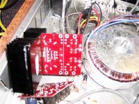
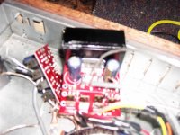
you can clearly see this on the pic of the underside of the rectifier board
Audiophilenoob said:you can clearly see this on the pic of the underside of the rectifier board
The pics are not very clear. 😀
The LM4780 has thin (and many) pins, check if there are shorted pins there. I don't mean on the board, I mean right on the chip.
Also, have you isolated the chip from the heatsink?
Are you sure it's well isolated?
Is the heatsink connected to the metal chassis?
It the chassis grounded?
carlosfm said:
The pics are not very clear. 😀
The LM4780 has thin (and many) pins, check if there are shorted pins there. I don't mean on the board, I mean right on the chip.
Also, have you isolated the chip from the heatsink?
Are you sure it's well isolated?
Is the heatsink connected to the metal chassis?
It the chassis grounded?
I've completely removed the board from the sink and it still does the same thing
I will look at the chip to make sure no pins are touching coming off
it's isolated by Artic silver cermanquie (non-conductive) thermal compound... so I'm assuming it's well isolated
the heatsink is not connected to the metal chassis... though one is glued... this isn't the one I was testing...
the chassis is grounded to a central star ground using 16 gauge wire
ok I put in the completely different transformer.... brand new
and wired it up to a completely new rectifier and board... no pins touching the amps good... looks great... should be it?
now the idle amp is making the 100w bulb like 2x brighter than before!
jesus I'm at such a loss
I'm nearly reading to just scrap the damn thing.... GAH
all this work.... man
and wired it up to a completely new rectifier and board... no pins touching the amps good... looks great... should be it?
now the idle amp is making the 100w bulb like 2x brighter than before!
jesus I'm at such a loss
I'm nearly reading to just scrap the damn thing.... GAH
all this work.... man
YES!!!
SUCCESS!!!!!!!!!!!!!!!!!!!!!!!!!!!!!!!!!!!!!!!!!!!!!
I figured out what was wrong!!!
VICTORY!
lol
as carlos suggested the chip amps were not isolated enough from the alum heatsink causing hell...
removed this one.... tested it.... no light bulb on... input from preamp
I'm getting a ticking back and forth 13v-15v out of the outputs (changing frequencies I suppose)
now I need to get some thermal tape or somethign to completely Isolate it...
incredibly happy man sitting here.... I thought it'd never work!
Audiophilenoob said:it's isolated by Artic silver cermanquie (non-conductive) thermal compound... so I'm assuming it's well isolated
Hang on, you mean the paste? I'd be surprised if that chip was isolated.
Try testing with your MM for a connection between your HS and the chip.
Most people use a silicone rubber washer for isolating the chip from the HS.
Keep at it, you'll get there 🙂
Michael
maf_au said:
Hang on, you mean the paste? I'd be surprised if that chip was isolated.
Try testing with your MM for a connection between your HS and the chip.
Most people use a silicone rubber washer for isolating the chip from the HS.
Keep at it, you'll get there 🙂
Michael
read above 😀
what's kind of silicone rubber washer??? I'm looking at thermal tape for the solution right now 😉
Something like this:
That one's from Parts Express, It's for a TO-220 package, I'm not sure what the 3875 is...
Michael
An externally hosted image should be here but it was not working when we last tested it.
That one's from Parts Express, It's for a TO-220 package, I'm not sure what the 3875 is...
Michael
- Status
- Not open for further replies.
- Home
- Amplifiers
- Chip Amps
- LOL.... I just fried 3 of my brianGT LM4780 boards