Some chip exists which may highly simplify your project, it contains 7 bandpass filter and peak detector. It is used in many Aliexpress audio spectrum analyzer, and it doesn't require an uC. With a demux and 7 sample & hold it can easily be connected to 7 LM3915.
https://www.sparkfun.com/datasheets/Components/General/MSGEQ7.pdf
https://www.sparkfun.com/datasheets/Components/General/MSGEQ7.pdf

About the LED current. The value of 20 mA AIM65 mentions is per LED. So full scale would require 240 mA for 1 channel. You would power the IC and the LEDs from a single supply which is well above the reference voltage. However, 20 mA is darn bright with modern LEDs. I also am used to calculate LED current at 20 mA like I did in 1974. But something has changed the last 50 years. LED current of 20 mA is sufficient to read the newspaper. Test the LEDs you will be using and make note of the current. Then calculate the resistors for your VU meter.
I am using my VU meter in my home cinema, so in the dark.The current through the LEDs is less than 2 mA IIRC. It is LED dependent so you have to test it.
I am using my VU meter in my home cinema, so in the dark.The current through the LEDs is less than 2 mA IIRC. It is LED dependent so you have to test it.
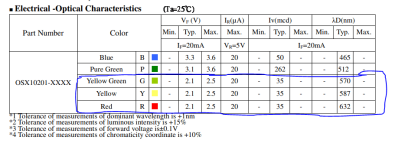
It's a bargraph with 10 leds: 5 green, 3 yellow, 2 red. All the leds are the same 2.1 - 2.5v voltage drop and 35 mcd i don't know how bright that would be .About the LED current. The value of 20 mA AIM65 mentions is per LED. So full scale would require 240 mA for 1 channel. You would power the IC and the LEDs from a single supply which is well above the reference voltage. However, 20 mA is darn bright with modern LEDs. I also am used to calculate LED current at 20 mA like I did in 1974. But something has changed the last 50 years. LED current of 20 mA is sufficient to read the newspaper. Test the LEDs you will be using and make note of the current. Then calculate the resistors for your VU meter.
I am using my VU meter in my home cinema, so in the dark.The current through the LEDs is less than 2 mA IIRC. It is LED dependent so you have to test it.
Yes I need to test them .
Attachments
Another possibility is to use a counter like the CD4017 and a comparator to enable the corresponding LED when a certain level is reached.
It was popular in the seventies/eighties, but I cannot locate an example for now.
It can be made to display a dot or a bar, and if the reference waveform is not a linear sawtooth, it can conform to any law, including log.
The circuit requires a clock generator, a decoded counter, a sawtooth generator, a comparator and a little glue logic
You often see circuits like that in FM IF circuits, the trick would be to find one that is usable at audio frequencies
Need more resolution: View attachment 1356658
Thanks for answering my implicit question of post #8, this is precisely the kind of circuit I meant!
Analogue logarithmic converters usually either use the exponential voltage-to-current characteristic of a bipolar transistor, as TerrySt wrote, or a limiter chain with rectifiers, often called an RSSI circuit.
When you make a long chain of amplifier stages with gain A that clip nicely when overdriven, put some rectifying circuit after each of them and add the rectifier outputs, you get an approximately logarithmic response. Suppose the output of a rectifier goes from 0 to Vrect when the input signal goes from 0 to the amplifier stage clipping level. Each factor of A increase of the input signal then increases the sum of the rectifier outputs by Vrect.
When the amplifier stage is a differential pair, you can use the emitter voltage of the next stage as rectifier output. You often see circuits like that in FM IF circuits, the trick would be to find one that is usable at audio frequencies
I have first hand experience with the device below and used it in a high-speed logarithmic detector---- the RSSI output has good log fidelity over many decades. Though it's presented as FM IF limiter/discriminator, I'm confident it can be applied at audio frequencies. The RSSI output will provide the log of the instantaneous signal amplitude (absolute value).
https://www.mouser.com/ProductDetail/Nisshinbo/NJM14570RB1-TE1?qs=OSezeAgrLvyzBGfJk3%2BFrA==
The question is what kind of decoupling capacitance you need at pins 7 and 8 and what the resulting settling time at start up will be.
Looking at the "Terminal function" table in the datasheet, it looks like DC feedback is done via 100 kohm resistors. The various graphs show that limiting starts around -80 dBm; assuming that is referred to 50 ohm because there is a 50 ohm termination in the test circuit, that is about 22.3 uV RMS, or about 30 uV peak.
Assuming it is actually the phase detector that starts the limiting, and assuming the detector is an ordinary Gilbert cell mixer that starts to limit somewhere around 60 mV peak, the limiter chain must have a voltage gain of about 2000 at low signal levels. With 100 kohm DC feedback resistance, the impedance at the DC decoupling pins is then about 50 ohm, so you need at least 200 uF at pins 7 and 8 if the lowest frequency of interest is 16 Hz. This is nothing more than an educated guess, of course.
With 100 kohm and 220 uF, the charging time constant is 22 seconds, so it may take a few dozen seconds or maybe a minute or so to settle after power on. If you don't care about the operation at 16 Hz at very low signal levels, you could use somewhat smaller capacitors.
When you just take the 10 nF that is recommended in the datasheet for 10.7 MHz IF, and scale it inversely proportionally with frequency, you end up using 6800 uF capacitors. The settling time will then be very long indeed.
@BSST , at what frequencies did you use it and how much capacitance did you need?
Last edited:
My application was not audio. Spectrum of interest was roughly 50kHz and upward, and thus limited to the bandwidth of the device—— about 25 to 30MHz. So the caps I used were small, probably 47nF. Your reasoning about required cap size seems correct. The technique may be unattractive for that reason. 😢
Need more resolution: View attachment 1356658
@jackinnj , do you happen to know how fast it settles after power on with 1 uF on pin 3?
Pin 3 is B+. Did you intend to ask about RSSI speed on pin 4?
The RSSI out is open collector with an internal 10.2 K load. I drove RSSI into the inverting input of a very fast opamp to avoid slow response. To my pleasant astonishment, I was able to detect very high speed pulses.
The RSSI out is open collector with an internal 10.2 K load. I drove RSSI into the inverting input of a very fast opamp to avoid slow response. To my pleasant astonishment, I was able to detect very high speed pulses.
There are two mentions of settling time in the data sheet, but I don't know if they answer your question.@jackinnj , do you happen to know how fast it settles after power on with 1 uF on pin 3?
This "Analog Dialogue" illustrates the point you made in Post 8: https://www.analog.com/en/resources/analog-dialogue/articles/logarithmic-amplifiers-explained.html
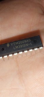
ic's arrived, logo doesn't look " legit " to me but hey , who knows.Hi,. A few days ago I ordered 20x LM3915
National Semiconductor ?.
Before TI bought them .
I doubt they are old stock National Semiconductor.
Attachments
Would this be ok ? . " Bridging " both channels like that andThe head amp before your band pass filters is a bit overkill. Using one or two opamp as buffers could be enough.
Putting the volume pot between op amps idk if it's usless or beneficial, but from a dual op amp , one channel isn't used . And I was thinking this way the pot won't affect the signal source .
Total Gain is 4 if my math isn't failing me , Thinking to use NE5532 , not sure they are ok for unity gain or if I need no gain in the buffer amp that feeds the LM3915's .
Attachments
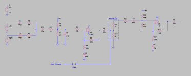
That is a very low impedance at the input. Summing two signals is mostly done by building a summing amplifier. That is, connecting 2 signals to the inverting input of an opamp. Google for summing amplifier. Resistors of 47k would be sound.
You could vary the gain by putting a pot in the feedback loop of the summing amplifier.
If you use the pot like you do you would need a buffer amp to get a constant low Z output. If you have the second half of the 5532 anyway and unused your solution if totally fine.
And yes, NE5532 is unity gain stable.
Like this ? Input impedance is dictated by R1 , R2 . 10K for each channel or 5K since they are kinda in parallel?.That is a very low impedance at the input. Summing two signals is mostly done by building a summing amplifier. That is, connecting 2 signals to the inverting input of an opamp. Google for summing amplifier. Resistors of 47k would be sound.
You could vary the gain by putting a pot in the feedback loop of the summing amplifier.
If you use the pot like you do you would need a buffer amp to get a constant low Z output. If you have the second half of the 5532 anyway and unused your solution if totally fine.
And yes, NE5532 is unity gain stable.
Attachments

- Home
- Design & Build
- Electronic Design
- Log conversion for VU/PPM meter