So I am in the process to design a VU/PPM meter. A few years ago this was easy. take some LM3915's. use the dot/bar mode for PPM/VU. Then do some precision rectifier and use 2 different circuits with different time constants.
Unfortunately the LM3915 is EOL 😡 (I recently read even the NE5534 is EOL).
The design would use Rectangle leds 2.5mm X 5mm and I would plan to use 40 of them. It will give me some resolution and a 10cm graph.
I know that using the normal LM3915 would also be tricky but using a different reference you can put them 1db apart and get a bigger scale. it is tricky but still doable.
So for now I am thinking what I can do as the LM3915 is EOL.
A solution could be to use separate comparators and a led string driven with a current source. for 40leds this means 10 quad comparators and use them in a few current strings as 30v will just hold 10leds. Then for the dot mode it will need some gates to make this happen....it's possible but it needs a lot of IC's so not a really good option.
So next plan is to see what can be done using the lm3914.
It is the lineair variant of the lm3915. Daisy chaining them to 40leds is not a problem. The only tricky part is to convert the signal from log to lin and do a PPM and VU detection on it.
So any ideas for Log/lin conversion are welcome.
There where some fantastic IC's (that 2252 etc) but they are obsolete or over the top expensive.
-Using a MCU is out of the question
-Using lm3915's sourced from ebay etc is also out of the question.
I want something build with parts that are not EOL
This doesn't directly answer answer your question but as to the LM3915, I would have thought at this point in time you could come up with some new stock. You rule out Ebay and that's fair enough but there are lots of cheapo boards/projects using these chips for sale. Could be worth taking a chance to scavenge the chips.
Donberg list them as available for example:

Donberg list them as available for example:
Hello Thanks for the info.
That pricing seems good and thanks for the info. I am thinking about stocking them. But it's not so easy to say how much....
It did give ma an idea as they are pin compatible I could make a display PCB using the lm391x and if the lm3915 isn't available anymore in the future I only would need to change the detection circuits.
Have a look at this project using the log RC-discharge voltage curve as reference:
https://www.eetimes.com/simple-high...-display-architecture-uses-analog-comparator/
Resolution and number of leds can be scaled as required (up to the limit of hardware).
just add a precision rectifier and a hold circuit if needed.
https://www.eetimes.com/simple-high...-display-architecture-uses-analog-comparator/
Resolution and number of leds can be scaled as required (up to the limit of hardware).
just add a precision rectifier and a hold circuit if needed.
Last edited:
I am building an analog meter that has a log scale as well as a PPM scale. For the log scale, I am using a transistor to do the linear to log conversion, and for the PPM scale, I am using an opamp with transistors to do a piecewise approximation of the PPM curve. I then drive an analog meter, but you could just substitute the linear bar-dot circuit.
Here is a description of the piecewise linear approach to PPM conversion:
https://www.bbceng.info/ti/eqpt/ME12_10.pdf
and here is an excellent design that has a 100dB log converter along with precision rectifier and peak hold circuits.:
http://www.tronola.com/html/level_meter.html
Terry
Here is a description of the piecewise linear approach to PPM conversion:
https://www.bbceng.info/ti/eqpt/ME12_10.pdf
and here is an excellent design that has a 100dB log converter along with precision rectifier and peak hold circuits.:
http://www.tronola.com/html/level_meter.html
Terry
Why is an MCU "out of the question"? My solution to almost exactly what you describe used a PIC16F1503, 10 LEDs and a handful of resistors. I was able to emulate the "ballistic" of a "real" PPM remarkably well, and I intend to extend the design to 20 or even 30 LEDs for greater accuracy. The PICs are easy to use, and a homebrew programmer is trivially easy to build. The PIC documentation is second-to-none, and this series of ICs remain my favourites despite their higher prices than the ATMega ICs.
LM3915 are still manufatured by many Chinese company such HGSemi http://www.hgsemi.com.cn/en/goods/list-65.html , and are available at LCSC : https://www.lcsc.com/products/Lighting-Drivers-Controllers_11129.html?keyword=3915
Analogue logarithmic converters usually either use the exponential voltage-to-current characteristic of a bipolar transistor, as TerrySt wrote, or a limiter chain with rectifiers, often called an RSSI circuit.
When you make a long chain of amplifier stages with gain A that clip nicely when overdriven, put some rectifying circuit after each of them and add the rectifier outputs, you get an approximately logarithmic response. Suppose the output of a rectifier goes from 0 to Vrect when the input signal goes from 0 to the amplifier stage clipping level. Each factor of A increase of the input signal then increases the sum of the rectifier outputs by Vrect.
When the amplifier stage is a differential pair, you can use the emitter voltage of the next stage as rectifier output. You often see circuits like that in FM IF circuits, the trick would be to find one that is usable at audio frequencies
Hi, I was searching on the LM3915, and found this thread , I have some dumb moment here because the led current and voltage scale are selected with the same resistors.
Currently I'm building a LED spectrum analyzer , and if someone here can make me understand better or help with the values for R1/R2
" Internal Voltage Reference from 1.2V to 12V ". So if I mess with R1/R2 I change the current trough the LED's and also the voltage ref, ( one combination of R1 and R2 will light all the leds on 2v input and other combination might light all the leds on 10v input ? ) , so the 3db/steps still remain ? .
Found something on Rod Elliott's website as well saying " The formula for sensitivity is somewhat complex, and is further complicated by the fact that the same resistors that change the reference voltage also affect the LED current. ".
https://sound-au.com/project60.htm
Attachments
@Vintage Audio Projec Hi,. A few days ago I ordered 20x LM3915 , I don't know if they are original or newly made in china ( fake ) , for the price of 0.64 eur / piece. Waiting on them.
270 more in stock , I'm not sure they ship in Belgium tho.
https://ardushop.ro/ro/electronica/682-vu-metru-lm3915-ic-dip.html?search_query=LM3915&results=3
270 more in stock , I'm not sure they ship in Belgium tho.
https://ardushop.ro/ro/electronica/682-vu-metru-lm3915-ic-dip.html?search_query=LM3915&results=3

Made in China doesn’t mean fake. Many Chinese manufacturer produces old part which are copy, not fake because they are branded with their brand not initial manufacturer.
ie. For lm3915 HGSemi does : http://www.hgsemi.com.cn/en/goods/list-65.html
this is very interesting for DIYers because those are old but very successful parts such as : upc1237, tda2050, lm13700, 40xx cmos, MAX7219,…
ie. For lm3915 HGSemi does : http://www.hgsemi.com.cn/en/goods/list-65.html
this is very interesting for DIYers because those are old but very successful parts such as : upc1237, tda2050, lm13700, 40xx cmos, MAX7219,…
Last edited:
yes, dB steps will remain. dB is an indication of a ratio. In this case, the ratio is input voltage / Ref. voltage.So if I mess with R1/R2 I change the current trough the LED's and also the voltage ref, ( one combination of R1 and R2 will light all the leds on 2v input and other combination might light all the leds on 10v input ? ) , so the 3db/steps still remain ? .
What matters, is what's said in Eliott sound site : supply voltage should be higher than ref voltage.
LM3915 are currently available @ LCSC : https://www.lcsc.com/products/Lighting-Drivers-Controllers_11129.html?keyword=3915.
@Vintage Audio Projec Sorry for using your post to ask . @AIM65 Can you please help me a bit .
This is the Bargraph I will be using , x10 bargraphs and x10 lm3915.


So , 2.1v at 20mA . Can you help with the calculations for the resistors on the lm3915 for 20mA for the led's , I was thinking 5V supply for the leds , same 5v or another 5v - 12v for the ic's .
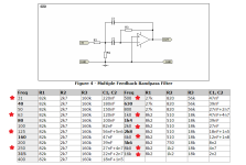
Filters I was looking at these from Rod Elliott's . they have a Q of 2 - 4 .

And for the input, a buffer that feeds the bandpassfilters, I was thinking to use this circuit. I'm not sure a single op-amp can do the job to drive 10x filters.

Since I don't know if I can post someone else's circuits. Here are the links to the schematics by Rod Elliott:
https://sound-au.com/project113.htm
https://sound-au.com/project64.htm
Thank you.
- Bruno.
This is the Bargraph I will be using , x10 bargraphs and x10 lm3915.
So , 2.1v at 20mA . Can you help with the calculations for the resistors on the lm3915 for 20mA for the led's , I was thinking 5V supply for the leds , same 5v or another 5v - 12v for the ic's .
Filters I was looking at these from Rod Elliott's . they have a Q of 2 - 4 .
And for the input, a buffer that feeds the bandpassfilters, I was thinking to use this circuit. I'm not sure a single op-amp can do the job to drive 10x filters.
Since I don't know if I can post someone else's circuits. Here are the links to the schematics by Rod Elliott:
https://sound-au.com/project113.htm
https://sound-au.com/project64.htm
Thank you.
- Bruno.
Attachments
This from the 1994 National Semiconductor "Linear Applications" -- I have a box of the TC resistor specified:

Now I hate those answers in forum where the OP ask for solving a problem and the answers indicate there IS no problem.
But in this case...
Where does the wisdom come from the 3519 is EOL? I googled and found that in 2012 the first announcements of EOL appeared. Two years ago (2022) I ordered a batch of 10 on Amazon. For prices USD 0.50-2.00 each. As of today there are at least a dozen offers on Amazon. And I am not even talking about Ali Express.
As for the Chinese version. Where else would you expect simple low-cost ICs to be manufactured?
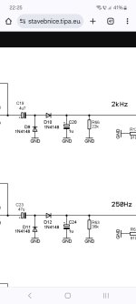
I have built a nice 2.1 channel VU meter with common brightness adjustment with these ICs. They serve the purpose perfectly. Also fast attach, slow decay function in the rectifier.
Note for anyone who wants to use the rectifier circuits: The gain for the mid and sub channels is different. I use the VU meter to indicate the power referred to the maximum power the speakers can handle. Because the power rating of the subwoofer is much higher, the VU meter indication is lower.
But in this case...
Where does the wisdom come from the 3519 is EOL? I googled and found that in 2012 the first announcements of EOL appeared. Two years ago (2022) I ordered a batch of 10 on Amazon. For prices USD 0.50-2.00 each. As of today there are at least a dozen offers on Amazon. And I am not even talking about Ali Express.
As for the Chinese version. Where else would you expect simple low-cost ICs to be manufactured?
I have built a nice 2.1 channel VU meter with common brightness adjustment with these ICs. They serve the purpose perfectly. Also fast attach, slow decay function in the rectifier.
Note for anyone who wants to use the rectifier circuits: The gain for the mid and sub channels is different. I use the VU meter to indicate the power referred to the maximum power the speakers can handle. Because the power rating of the subwoofer is much higher, the VU meter indication is lower.
Attachments
Yes, the formula is complicated. I chose to decouple the brightness and gain.step control. In my previous post I posted the schematic. I create a 9.0 reference voltage from the REF OUT. The current from REF OUT is set by a current source which does not affect the reference voltage.Hi, I was searching on the LM3915, and found this thread , I have some dumb moment here because the led current and voltage scale are selected with the same resistors.
Currently I'm building a LED spectrum analyzer , and if someone here can make me understand better or help with the values for R1/R2
" Internal Voltage Reference from 1.2V to 12V ". So if I mess with R1/R2 I change the current trough the LED's and also the voltage ref, ( one combination of R1 and R2 will light all the leds on 2v input and other combination might light all the leds on 10v input ? ) , so the 3db/steps still remain ? .
Found something on Rod Elliott's website as well saying " The formula for sensitivity is somewhat complex, and is further complicated by the fact that the same resistors that change the reference voltage also affect the LED current. ".
https://sound-au.com/project60.htm
View attachment 1356126
Last edited:
To calculate the two resistors, you need to decide the max voltage at the input : voltage which correspond to 0dB. Let’s say 5V; then chip supply should be more than this, let’s say 6 or 7V. 6 or 7V are ok for led supply, which should not exceed 7V in bar graph mode. A single 7806 or Zener+bjt should be enough for this.So , 2.1v at 20mA . Can you help with the calculations for the resistors on the lm3915 for 20mA for the led's , I was thinking 5V supply for the leds , same 5v or another 5v - 12v for the ic's .
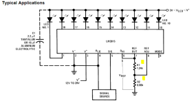
According to TI datasheet page 2, R1 and R2 could be evaluated using Vref=5V and iLed=20mA.
Use R1=680Ω and R2=1800Ω + 150Ω.
You can also play with this : https://www.electro-tech-online.com/tools/LM3915V2.php but accuracy is too low
Or if you own a Windows PC with Windows < W8, you can use ESP software : https://sound-au.com/download.htm !
The head amp before your band pass filters is a bit overkill. Using one or two opamp as buffers could be enough.
Between each band pass and it’s LM3915 Vu meter you’ll certainly need a peak detector such as the one described in fig17 of the TI datasheet.
Would this also work ?Between each band pass and it’s LM3915 Vu meter you’ll certainly need a peak detector such as the one described in fig17 of the TI datasheet.
Attachments
Thank you for your time.According to TI datasheet page 2, R1 and R2 could be evaluated using Vref=5V and iLed=20mA.
Use R1=680Ω and R2=1800Ω + 150Ω.
So with R1 680 and R2 1950 , 5V input would be 0 db , and 20mA for the leds at 5v led supply ? . and 6-7 v for the ic.
I don't think so, this circuit gives you twice peak value (peak to peak) minus 2 * diode forward voltage.Would this also work ?
The diodes induce a voltage drop of about 600mV on the peak value (1.2 on peak to peak). 600mV with a 0dB FS at 5V corresponds to about -18dB, Vu meter display will be erroneous : shifted down by 18dB (6 leds...). That's why an active rectifier is required, such as the ones described in the datasheet.
- Home
- Design & Build
- Electronic Design
- Log conversion for VU/PPM meter