Interesting in that high voltage zeners are much less stable with temperature than 85A2. Something I discovered rather than knew.
The other thing to say is that some of the circuits shown may not start up unless there's some current getting to the zener/85A2 from the input supply. Its also useful so the 85A2 strikes early so that there is no initial step in the output voltage.
What is the best way to insure that the zener/85A2 are getting sufficient current at initial start up?The other thing to say is that some of the circuits shown may not start up unless there's some current getting to the zener/85A2 from the input supply. Its also useful so the 85A2 strikes early so that there is no initial step in the output voltage.
Not sure, some of the current can come from the input supply. It was an issue when you have a semiconductor regulator. You would have to simulate to see if it's an issue with your topology. You could ramp the input voltage up and see if there's any odd behavior. Sometimes these circuits don't start up because everything is off. It may be because the pass device is valve even when the grid is 0V the cathode is positive and there is some output voltage.
If you want simple one there are many, but whether simple or complex one should be able to source easily available components rather than rare and expensive one. 85A2 temperature coefficient is -2.7mV/K which is ~32PPM, where ZZ8000 is -3mV/K, and TL431 5mV/K, which one would you prefer?Thanks. Yes, CCS on the anode. Will any CCS do? Also, does your sim show the ZZ1000 as reference? My preference would be to have the supply be all tube and as simple as possible. Loesch’s supply seems overkill for my application, and I would prefer to not use EF86 because it seems a bit wasted in this use. It also seems that the ZZ1000 is a good option because of its performance and stability as compared to zeners. Wouldn’t VR tubes be similarly stable and simple to implement, without being sonically inferior?
I don't have a model for ZZ8000.
1) The gain for EF86 is mediocre, I'll recommend 6f12p or EF184 and other pentode tube with similar gain.
2) No need to use CCS if you go for high gm/gain tube, and increase anode resistor say from 330k to 680k.
3) Use 2xTL431 as reference, noted the reference voltage is now lower and trimmer network adjusted to suit, I hope it'll cover the range you need.
I hope these will improve / solve 1) voltage regulation resolution and 2) temperature variation for your simple regulator.
Attachments

Last edited:
What makes a pass tube a pass tube? It seems EL34 and 6L6 are often used as pass tubes, but aren’t large double triodes like 6AS7, 6080, 5998, etc.You also use a pass tube with smaller footprint such as 6c19p to save space.
6c19p and 6c33c are real regulator tube as pass tube, e.g. the heater to cathode is 200v. Others are pentode/tetrode triode connected, if the current and heater-cathode voltage meet the requirement they can be used a pass tube. Their max plate voltage is about 500v. I believe they may have lower heater-cathode voltage so will need a heater lift to become safe. Glad you ask so don't forget this to include this in your project.
Last edited:

Less is more, the circuit may out perform previous version.
https://www.angelfire.com/electronic/funwithtubes/bench_psu.html
https://www.angelfire.com/electronic/funwithtubes/images/bpsu-22.gif
https://www.angelfire.com/electronic/funwithtubes/bench_psu.html
https://www.angelfire.com/electronic/funwithtubes/images/bpsu-22.gif
Attachments
Thanks again! I assume that I can replace the 6C19P with a 6AS7 or 6080? I have dozens of them and no 6C19P. If so, are any circuit changes required? I will study the article to learn more. With respect to the bpsu-22.gif supply, can I replace the 5651 with a ZZ1000? I found 8 in total in my stash, so that seems the easy and cheapest way to go.Less is more, the circuit may out perform previous version.
https://www.angelfire.com/electronic/funwithtubes/bench_psu.html
https://www.angelfire.com/electronic/funwithtubes/images/bpsu-22.gif
Yes you can use a single EL34 to provide enough current for two 6V6. The pass tube is not really critical, 6080 6C19P 6L6 KT88 will work too.This schematic looks great. My intended application is in a 6V6 preamp. Would it be scalable to reflect this use? The preamp has relatively low B+ requirements, and this power supply would use three EL34s to provide power to two 6V6s. It seems that it would be great for a powerful PP amp, but a scaled down version might be better for my use. Also, with respect to voltage variations caused by the thermal drift of zeners, what would be the practical impact with respect to sonics of this drift for a 6V6 preamp? Assuming that the B+ doesn’t reach the maximum allowable dissipation for the tube in this circuit, will a slow rise in B+ over time adversely affect sonics? My understanding of the benefits of tube regulated supplies for single ended circuits is that the benefits are with providing a low impedance power supply for the circuit more than with a constant voltage over time. Again, I’m a noob with respect to regulated supplies, so please correct me if I’m wrong.
PM if you want me to design a board for you.
Attachments

That depends on application, for a wide adjustment lab grade power supplies, pentodes like EL34 with a floating screen supply are king, wheras for fixed supplies the aforementioned big triodes are most efficient.What makes a pass tube a pass tube? It seems EL34 and 6L6 are often used as pass tubes, but aren’t large double triodes like 6AS7, 6080, 5998, etc.
The 6080 for example is ideal if you have 100V higher Vin than Vout. Wheras a EL34 can see much more voltage. It was used extensively in mil equiptment to stabilize voltages for radar equiptment ect.
The 6080 is well suited to be a stabilizer valve with its big cathodes, it was purpose designed to be an efficient stabilizer valve, there are some higher transconductance versions that will offer slightly improved performance. But that performance increase is negligible for class A loads.
Yes, 1x6c19p (11W) is about same as 1 section of 6080 (13w) , you need 2x6c19p to replace a 6080. 6c19p has a bit more gain, should be ok. 5651 is 87 volt while zz8000 is 82v so about same. But I found a weak point the circuit it draws too much idle current by itself, the VR tube should be lowered as the to reduce the current in the comparator. I already lowered it to 56V, even lower if I can. Now the idle current drawn across R1 is 70mA which is too high to be useful for our purpose, and certainly not for single 6c19p. I'm referring to this circuit : https://www.angelfire.com/electronic/funwithtubes/images/bpsu-22.gifThanks again! I assume that I can replace the 6C19P with a 6AS7 or 6080? I have dozens of them and no 6C19P. If so, are any circuit changes required? I will study the article to learn more. With respect to the bpsu-22.gif supply, can I replace the 5651 with a ZZ1000? I found 8 in total in my stash, so that seems the easy and cheapest way to go.
Last edited:
What would the fixed circuit look like?Yes, 1x6c19p (11W) is about same as 1 section of 6080 (13w) , you need 2x6c19p to replace a 6080. 6c19p has a bit more gain, should be ok. 5651 is 87 volt while zz8000 is 82v so about same. But I found a weak point the circuit it draws too much idle current by itself, the VR tube should be lowered as the to reduce the current in the comparator. I already lowered it to 56V, even lower if I can. Now the idle current drawn across R1 is 70mA which is too high to be useful for our purpose, and certainly not for single 6c19p. I'm referring to this circuit : https://www.angelfire.com/electronic/funwithtubes/images/bpsu-22.gif
You can aviod current drawn from regulated output by diverting some connections to unregulated input. E.g connect R4 to the HT unregulated will reduce current drawn from reg output by 11ma. The remain current of about 10mA in R6 can not be done in the same way as it's part of input sensor which must be connected to reg. output and only way I know is If the sensor comparator voltage is reduced, less current would be required. I don't know how low the sensor / VR can be at this moment.
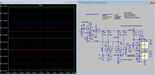
I think found a way to resolve high current issue in comparator, see attached it's self-explanatory. Thank you for looking or studying.
ps: the regulator will have best resolution when the comparator bias is adjusted to -1v. In order to further improve regulation, a VR can be used in the cathode to replace resistors.
ps: the regulator will have best resolution when the comparator bias is adjusted to -1v. In order to further improve regulation, a VR can be used in the cathode to replace resistors.
Attachments

Last edited:
I need to study to better understand how these regulators work, and will do so. I'm not sure what you mean when you say "ps: the regulator will have best resolution when the comparator bias is adjusted to -1v." The comparator is the 12AX7, so it should be biased to -1V? Do you mean triode U4, or both U4 and U2 triodes?I think found a way to resolve high current issue in comparator, see attached it's self-explanatory. Thank you for looking or studying.
ps: the regulator will have best resolution when the comparator bias is adjusted to -1v. In order to further improve regulation, a VR can be used in the cathode to replace resistors.
Yes, but U4 (1st tube) is more critical.I need to study to better understand how these regulators work, and will do so. I'm not sure what you mean when you say "ps: the regulator will have best resolution when the comparator bias is adjusted to -1v." The comparator is the 12AX7, so it should be biased to -1V? Do you mean triode U4, or both U4 and U2 triodes?
- Home
- Amplifiers
- Tubes / Valves
- Loesch Legacy 300B power supply mod for preamp