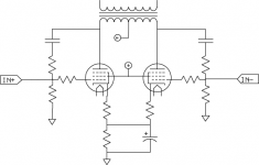
Does anybody have strong opinions/suggestions on implementing local feedback on a push pull amp -- likely EL84 based. For various reasons, I am interesting in playing with a circuit stage by stage, so I'd like to leave the driver out of it for the time being. I have seen plate to grid feedback done via resistor + cap, and I am wondering if this is preferable to connecting OPT secondaries to the grids via just a resistor (which seems more likely to correct for OPT distortion) or if there are other ways I have not thought of.
Attachments
Does anybody have strong opinions/suggestions on implementing local feedback on a push pull amp -- likely EL84 based. For various reasons, I am interesting in playing with a circuit stage by stage, so I'd like to leave the driver out of it for the time being. I have seen plate to grid feedback done via resistor + cap, and I am wondering if this is preferable to connecting OPT secondaries to the grids via just a resistor (which seems more likely to correct for OPT distortion) or if there are other ways I have not thought of.
There are any number of ways to implement lNFB. The implementation you showed is the one I used with the Vixen design that used PP 807s as finals. DC isolation allows for increased design flexibility, as you can operate without the lNFB loop to see if it's necessary and/or how much it improves sonic performance. Just make sure that your DC isolation capacitor has a generous voltage rating: VDC + Vp + safety factor.
The thing to keep in mind always when doing plate/grid lNFB is that the feedback loop increases the load on the driver. You may have to include a grid driver follower to isolate a gain stage from that increased load. Miller Effect will decrease the effective size of that feedback resistor the same as it does the reverse transfer capacitive reactance, and by the same factor (1 + AV).
You could opt for some form of UL, the most common being a direct connection between the screens and a tap-off of the OPT primary. This requires finals that can operate their screens at the same potential as the plates (6V6-oids here, 50C5, 50L5, etc). Otherwise, UL requires either a separate tertiary for the screens or the use of a MOSFET follower to supply screen current at a lower DC screen potential. The main problem with most forms of UL is that it can't be adjusted, and you have no choice but to hope the designers of the OPT got it right for your choice of finals.
The other possibility is cathode feedback, if you have an OPT with a balanced secondary (or you can fake it with a multi-tap secondary). This, too, is limited in that the secondary voltage is dependent on the load impedance. You take what you get.
All lNFB implementations accomplish the same things: reduce the effective plate resistance, compensate for nonlinearities, make the dynamic characteristics of a pentode more like that of a triode. Whether it's necessary or not depends on what finals you're using. Types like the 6L6-oids need the extra help as they tend to make a lot of the nastier high order harmonics. I found that 6BQ6GAs (TV HD final) like the 6V6-oids, make mainly h3 and really don't need lNFB. Just enough gNFB to take the edge off.
Something like 5-10% cathode feedback, depending on what you want/need, by means of OT windings. I find it is more practical, "easier" and effective than plate to grid feedback in most cases.
You could use the transformer secondaries to do this if they allow a symmetrical layout (each side with the right phase) and the center tap grounded (where you connect the negative of the speaker). You will waste some efficiency but it can be quite cheap!
You could use the transformer secondaries to do this if they allow a symmetrical layout (each side with the right phase) and the center tap grounded (where you connect the negative of the speaker). You will waste some efficiency but it can be quite cheap!
A while ago I tested various EL34 output constructions and one of those was this:
The output transformer I used had four parallel secondaries and I used one of those to create LNFB for the other output tube. This circuit creates 6 dB of LNFB while UL with 40 % taps created below 3 dB.
I made some comparison between pentode connected, UL- and pentode with cathode NFB. All tested circuits had equal amount of total NFB, while the local NFB varied from zero of pentode to 6 dB of the cathode connected pentode.
The cathode NFB gave essentially better results than UL and especially with 4 ohms load. The OPT is 4k to 8 ohms.
Below some test results:
An externally hosted image should be here but it was not working when we last tested it.
Last edited:
The lower cost OTs I have seen tend to have the inner UL sections (near B+) wound closest to the secondary. (low leakage L measured to secondary, easy to test with an L meter) So taking resistive (+ iso cap) local feedbacks from the UL connections should be a good idea as long as you don't get phase instability problems.
If you place the capacitor between transformer primary and R fb, you ll need yet another 2 capacitors to the driver tubes. This configuration allows DC feedback to anodes of driver tubes and only one capacitor per side, to grids.
The driver stage is solid state and has plenty of driving ability.
The OPTs are these. They do have UL taps, but I have no idea if they are any good.
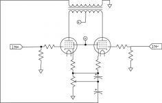
I do like the idea of cathode feedback, but the secondaries on these OPTs don't make it easy. One work around for that was something like the attached to allow for some adjustment. The biggest concern there (which is also a concern for running the secondaries back to the grids) is that it makes switching between the 8 and 4 Ohm taps involve some sort of switch, rather than just wiring them both up with a extra speaker post.
The OPTs are these. They do have UL taps, but I have no idea if they are any good.
I do like the idea of cathode feedback, but the secondaries on these OPTs don't make it easy. One work around for that was something like the attached to allow for some adjustment. The biggest concern there (which is also a concern for running the secondaries back to the grids) is that it makes switching between the 8 and 4 Ohm taps involve some sort of switch, rather than just wiring them both up with a extra speaker post.
Attachments
Perhaps one needs to repeat the difference between UL and "outside" feedback regarding pentode output stages.
With outside voltage feedback the pentode still has pentode internal characteristics - it does not know what happens outside and will exhibit the same disadvantages regarding sensitivity to un-uniform load etc. Yes, these are reduced by the feedback factor but still exist, if to a lesser degree.
In UL the characteristics of the tube itself is altered. It has a more triode-like appearance, e.g. with internal resistance (rp) much lower than that of a pentode, thus its distortion less dependant on an alien load. (This is inter alia well illustrated in graphs for the KT88 for various percentages of screen tap - I regret not having the reference at hand now.)
There are no distinct 'optimal' taps for UL. The characteristics change smoothly as the tap point increases, and the preferred point is of one's own choosing, although maximum available output generally starts to fall sharply above some 45% taps, thus negating the advantages.
For that reason I rather prefer using a screen-tapped OPT than an equivalent amount 'outside NFB'. (This apart from the more demanding driving impedance.) It does of course mandate the same voltages for anode and screen.
Keep in mind that with these transformers, due to high impedance ratio, you will not get a lot of voltage feedback (the input voltage is stepped down too much)
The driver stage is solid state and has plenty of driving ability.
The OPTs are these. They do have UL taps, but I have no idea if they are any good.
I do like the idea of cathode feedback, but the secondaries on these OPTs don't make it easy. One work around for that was something like the attached to allow for some adjustment. The biggest concern there (which is also a concern for running the secondaries back to the grids) is that it makes switching between the 8 and 4 Ohm taps involve some sort of switch, rather than just wiring them both up with a extra speaker post.
You might also get cathode feedback to work by using your original scheme, but cross-coupling; from tube A anode to tube B cathode, and vice-verse.
Cross coupling will only work well if the stage is running in class A. Cross coupling to the driver stage cathodes (which is in class A) would work well.
I used Ultralinear plus balanced shunt feedback in this amp - No Global Feedback
http://www.diyaudio.com/forums/tubes-valves/72536-el84-amp-baby-huey.html
It gave me the best results I've been able to screw out of a tube HiFi Power Amp.
My current amp is a 6V6, 6SL7 version of the schematic I posted at post #602 here
http://www.diyaudio.com/forums/tubes-valves/72536-el84-amp-baby-huey-61.html
Self recommendation is always dodgy but these amps really are stunning.
Cheers,
Ian
It gave me the best results I've been able to screw out of a tube HiFi Power Amp.
Can you post some of those results ?
Especially I am interested about Zout and THD without any GNFB.
I used Ultralinear plus balanced shunt feedback in this amp - No Global Feedback
http://www.diyaudio.com/forums/tubes-valves/72536-el84-amp-baby-huey.html
It gave me the best results I've been able to screw out of a tube HiFi Power Amp.
My current amp is a 6V6, 6SL7 version of the schematic I posted at post #602 here
http://www.diyaudio.com/forums/tubes-valves/72536-el84-amp-baby-huey-61.html
Self recommendation is always dodgy but these amps really are stunning.
Cheers,
Ian
My amps are built on similar principles - but with more Plate to Grid feedback. They certainly deliver without giving up on detail, but gaining massive bass authority.
Shoog
Cross coupling will only work well if the stage is running in class A. Cross coupling to the driver stage cathodes (which is in class A) would work well.
OK, that makes sense.
If you place the capacitor between transformer primary and R fb, you ll need yet another 2 capacitors to the driver tubes. This configuration allows DC feedback to anodes of driver tubes and only one capacitor per side, to grids.
Watch out! You have 800V from the output transformer through the 240K feedback resistor to the input!
800V of Ub yields a max of nearly 1600V max signal amplitude. This is far too much feedback and needs to be attenuated.
Furthermore, this kind of feedback (parallel derived, parallel applied) can make things a lot worse because it lowers the input resistance (and of course, also output resistance). If you you don't have a dead stable driver with very low r-out, you will increase distortion.
Furthermore, this kind of feedback (parallel derived, parallel applied) can make things a lot worse because it lowers the input resistance (and of course, also output resistance). If you you don't have a dead stable driver with very low r-out, you will increase distortion.
800V of Ub yields a max of nearly 1600V max signal amplitude. This is far too much feedback and needs to be attenuated.
Furthermore, this kind of feedback (parallel derived, parallel applied) can make things a lot worse because it lowers the input resistance (and of course, also output resistance). If you you don't have a dead stable driver with very low r-out, you will increase distortion.
A constant current, ie pentode driver, is the correct approach to driving the feedback grid node.
Shoog
I think the "input 1" in post 16 above, where the feedback R is applied, was intended to be the plate of the previous amplifier stage. Not a user input.
The shunt Fdbk does indeed lower the impedance considerably at that point as the-manta said. Hence the usual driving it with a current source (or pentode). A true voltage source would swamp out the feedback. That pentode needs to be very much linearized though.
The most accurate place to send the shunt feedback resistor back to would be the cathode of the previous driver stage. Then it lowers the Z in a useful place, and then compares input V with output V in the most accurate sense over both stages. Unfortunately that arrangement seems to sound "worse" to many, since it removes much of the low harmonic distortion "tail", and so removes the mysterious "detail" feature. No tail, no detail. You can always just lighten up on the amount of N-Fdbk though.
Last edited:
I think the "input 1" in post 16 above, where the feedback
The most accurate place to send the shunt feedback resistor back to would be the cathode of the previous driver stage. Then it lowers the Z in a useful place, and then compares input V with output V in the most accurate sense over both stages. Unfortunately that arrangement seems to sound "worse" to many, since it removes much of the low harmonic distortion "tail", and so removes the mysterious "detail" feature. No tail, no detail. You can always just lighten up on the amount of N-Fdbk though.
You can turn the output stage into a pure I-V converter with plate to grid feedback and it will still sound remarkably clean and detailed. I think the problems are somewhat overstated.
Gary Pimms Tabor takes this logic to its natural conclusion and sounds remarkable.
Shoog
- Status
- Not open for further replies.
- Home
- Amplifiers
- Tubes / Valves
- Local Feedback for Push Pull Pentode