Do anyone know what the loadline would be like when there is cathode degeneration / local negative feedback? I guess that effectively means under AC the grid curves will become more crowded towards the curve which the tube is at that particular Vg (which is dynamic and following the AC signal), that means the headroom of a particular bias set towards Vg=0 remains the same compare for the one without cathode degeneration. And for DC, the curve will just like the one without cathode degeneration. Is that correct?
Attachments
I've been looking into that in the past. I found this: https://worldradiohistory.com/Archive-Rider/BOOKS/Inside-the-Vacuum-Tube-Rider-1945.pdf
p327.
See this thread: Load line plotter for unbypassed gain stage | Telecaster Guitar Forum
p327.
See this thread: Load line plotter for unbypassed gain stage | Telecaster Guitar Forum
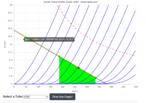
Let my pic as an example. The Vg is now set at -10V. What I am concerning is that if I would like to unbypass the cathode resistor to reduce the gain / to lower distortion, but still need to maintain the total output, would the Vg now be required to swing more (from +-10v to +-20v, assume the gain now reduced by half due to the feedback effect), which at the current operation point, would not be able to provide such headroom (still +-10v as it is set at Vg= -10). I think it is important in the design of driving stage to consider the headroom available if cathode degeneration is also in the design.
I guess the answer is that once the Vg is set, that Vg line will be fixed (because it is the DC quiescent point which the bypass cap has no effect at all), and all other curve will come more crowded towards this Vg curve (as the amplification is now lower). This means that the headroom to the Vg=0 in fact remains unchanged. And therefore for driving stage with option of cathode degeneration, more headroom is in fact needed in the setting of operation point. Look forward for any comment.
I guess the answer is that once the Vg is set, that Vg line will be fixed (because it is the DC quiescent point which the bypass cap has no effect at all), and all other curve will come more crowded towards this Vg curve (as the amplification is now lower). This means that the headroom to the Vg=0 in fact remains unchanged. And therefore for driving stage with option of cathode degeneration, more headroom is in fact needed in the setting of operation point. Look forward for any comment.
Last edited:
The bias point will indeed be unchanged, for exactly the reason you state. The load line will also not change. It is only affected by the plate resistance and load resistance. The only thing that changes are the grid curves. The altered grid curves are much closer together. This also means that the headroom is increased. The altered grid curves depend on the cathode resistance. Other resistance, other grid curves.
The bias point will indeed be unchanged, for exactly the reason you state. The load line will also not change. It is only affected by the plate resistance and load resistance. The only thing that changes are the grid curves. The altered grid curves are much closer together. This also means that the headroom is increased. The altered grid curves depend on the cathode resistance. Other resistance, other grid curves.
I think the headroom is increased only for the right hand side, that means more headroom from the negative Vg (count from the bias Vg). The headroom towards Vg=0 should be the same, as Vg bias is still at that operation point. Do you agree? That also means that setting the operation point using bypassed curve and then unbypass the cathode resistor in fact may worsen the distortion at max output by driving the tube towards Vg positive region.
Last edited:
Take a stage with about 1 dB of negative cathode feedback (about 10% voltage negative feedback).
Have the grid 10 Volts more negative than the cathode, and No cathode feedback.
A +10V signal drives the grid to zero volts with respect to the cathode.
More than that distorts the signal (arguable, depends on the tube, circuit, and a driver with low distortion and low impedance to driving grid current).
Now, With 1dB negative cathode feedback, the drive signal can go to +11Volts, and the grid goes to zero volts with respect to the cathode, because the cathode was raised up by +1V of negative cathode feedback.
Of course, you have to also consider when the drive goes to -10V for the Non-negative cathode feedback stage,
verus when the drive goes to -11V for the Negative cathode feedback stage.
Is that helpful to understand an important factor when using negative cathode feedback?
I believe that any tube that is operated in the high rp section of the tube curves will distort, and not be able to be cured by just adding negative feedback.
It needs to be biased further up the family of curves (or pick another tube type).
This is especially true for single ended operation.
Push Pull Class AB1 amplifiers, and Pseudo Class B amplifiers, are arguably good examples of how to be able to use the high rp areas when negative cathode feedback is employed.
Just my opinion.
Last edited:
Take a stage with about 1 dB of negative cathode feedback (about 10% voltage negative feedback).
Have the grid 10 Volts more negative than the cathode, and No cathode feedback.
A +10V signal drives the grid to zero volts with respect to the cathode.
More than that distorts the signal (arguable, depends on the tube, circuit, and a driver with low distortion and low impedance to driving grid current).
Now, With 1dB negative cathode feedback, the drive signal can go to +11Volts, and the grid goes to zero volts with respect to the cathode, because the cathode was raised up by +1V of negative cathode feedback.
Of course, you have to also consider when the drive goes to -10V for the Non-negative cathode feedback stage,
verus when the drive goes to -11V for the Negative cathode feedback stage.
Is that helpful to understand an important factor when using negative cathode feedback?
I believe that any tube that is operated in the high rp section of the tube curves will distort, and not be able to be cured by just adding negative feedback.
It needs to be biased further up the family of curves (or pick another tube type).
This is especially true for single ended operation.
Push Pull Class AB1 amplifiers, and Pseudo Class B amplifiers, are arguably good examples of how to be able to use the high rp areas when negative cathode feedback is employed.
Just my opinion.
I read your comment and try to think about what happen to the cathode voltage and its relationship with amplification. It seems that, when the signal start from zero to positive, and drive the Vg towards positive from the bias point, under cathode unbypassed condition, the cathode resistor will suck up more current and then push the cathode voltage upwards, making it effectively reducing the voltage difference between the cathode and the grid, and so lower the amplification.
Let's assume the Vg is originally set at Vg=-10, if the amplification is halved by cathode degeneration, when the signal try to drive the Vg to 0, the cathode side will have its voltage up by 5, effectively reduce the amplification by half. So the remaining headroom from this point to Vg=0 is still 5. If the signal continue to up further another 5V, the cathode side up by 2.5V, leaving 2.5V headroom towards Vg=0. All this summed up to the conclusion that the headroom is in fact increased. The increase in headroom should be approx. by the reduction in amplification by the feedback formula. Is that a good approximation to the working principle of cathode degeneration?
Besides, what do you mean by "high rp section of the tube curves "?
Last edited:
I think you get it.
Let's try some other wording to make sure. Two ways to look at it.
1) the feedback signal is subtracted from the input signal. A smaller effective signal clips later; on both sides.
2) the input signal swings positive wrt ground. The grid to cathode voltage stays negative.
High rp means the same as high ra (plate/anode). High ra part is the lower curvy part of the normal grid curves as can be seen in 1.4 of this: http://www.valvewizard.co.uk/Common_Gain_Stage.pdf
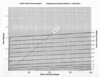
But the grid curves in the unbypassed case are altered. They look completely different and are dependent on the cathode resistance.
Let's try some other wording to make sure. Two ways to look at it.
1) the feedback signal is subtracted from the input signal. A smaller effective signal clips later; on both sides.
2) the input signal swings positive wrt ground. The grid to cathode voltage stays negative.
High rp means the same as high ra (plate/anode). High ra part is the lower curvy part of the normal grid curves as can be seen in 1.4 of this: http://www.valvewizard.co.uk/Common_Gain_Stage.pdf
But the grid curves in the unbypassed case are altered. They look completely different and are dependent on the cathode resistance.
Attachments
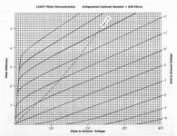
That is an extreme case, I guess with Rk at 10k in the last image, you are limiting transconductance with the large value.
My conclusion from that is you want to run as high a quiescent current as possible, and as small Rk as possible.
A difficult thing to do, with 12AX7 under the usual anode voltages used.
Maybe then, the technique of using degenerated cathode is better suited to higher mA valves?
I.e. take a valve with an initially low ra, 6N3P maybe.
Last edited:
A grid that is 10Volts more negative than the cathode is not for 12AX7 tubes (it will be far beyond cut-off).
Instead, try a single ended output stage, like a triode wired 7591A, with -10V bias, and an output transformer.
For discussion, let us use an added special secondary that drives the cathode, and reduces the stage gain by 1dB. Donnect the bottom of the self bias network from ground, and connect it to the top of the special secondary, with the other end of the special secondary grounded.
Except for the DCR of that special secondary, the cathode self bias remains unchanged (but we can reduce the self bias resistor to compensate for that).
The Bypass cap remains the same (frequency response of the self bias network does not change more than the change in self bias resistor does).
if the cathode negative feedback is -1dB, that means the gain from that stage is 89% of what it was before the negative feedback was applied to the cathode.
You can apply a drive signal that is 1.12 times + 10V, and 1.12 times -10V (+ and - 11.2V).
This is not the complete solution to the problem, but is food for thought to get you thinking.
At some point, depending on the original parameters of bias, plate voltage, plate current, etc. the tube may, or may not, be driven into clipping at or near tube cutoff; or when grid current is drawn.
Whatever the plate resistance was before applying -1 dB feedback, after applying negative feedback, the Effective plate resistance is 0.89 times what it was before applying -1 dB of negative feedback.
If instead, we reduce the output stage gain to 1/2 of what it was before applying negative feedback, then the negative feedback value is -6dB.
And likewise, the Effective plate resistance is 1/2 of what it was before applying -6dB of negative feedback.
Yes?
No?
Any complete analysis requires the schematic with all parts values listed, tube curves, and the quiescent voltages and quiescent currents.
Last edited:

I've been looking into that in the past. I found this: https://worldradiohistory.com/Archive-Rider/BOOKS/Inside-the-Vacuum-Tube-Rider-1945.pdf
p327.
See this thread: Load line plotter for unbypassed gain stage | Telecaster Guitar Forum
That first link you gave will download an empty pdf file
or am I doing something wrong?
Yes 🙂
I tried it and it still works. I could send it to you, e.g. via WeTransfer. I would need your email address. It's 8Mb, probably too big for mail.
I think you can guess my hotmail email address.
I tried it and it still works. I could send it to you, e.g. via WeTransfer. I would need your email address. It's 8Mb, probably too big for mail.
I think you can guess my hotmail email address.
- Home
- Amplifiers
- Tubes / Valves
- Loadline under cathode degeneration/ local negative feedback