Those are the one's which would regularly blow the emitter resistor! There was an elektor article using them and the LM4702
Yes, I just saw your old post from 2007.
Better stick with conventional darlingtons then.
I still have some Sanken MP1620/MN2488 which were popular with the LM4702.
They should work with the LME49811 as well.
Better stick with conventional darlingtons then.
I still have some Sanken MP1620/MN2488 which were popular with the LM4702.
They should work with the LME49811 as well.

LME498X0 is indeed an excellent product.
After the discontinuation, I tried to use the 49830 to drive the BJT output stage because the qualified 49810 was not available on the market.
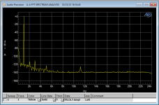
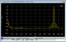
49830+EF-II output stage, connected to resistive load can measure THD+N 0.000X%
After the discontinuation, I tried to use the 49830 to drive the BJT output stage because the qualified 49810 was not available on the market.
49830+EF-II output stage, connected to resistive load can measure THD+N 0.000X%
Let me show a way (translate needed)I would like to hear the experience of others using the two pole compensation scheme.
https://forum.vegalab.ru/showthread.php?t=87194
Direct Google Translate link:
https://forum-vegalab-ru.translate...._sl=ru&_x_tr_tl=en&_x_tr_hl=ru&_x_tr_pto=wapp
The compensation certainly isn't "set and forget". I am getting slew rates of 23 V/us on one channel and 27 V/us on the other.
and while I am at it -- one of the DIYAUDIO contributors worked on the development of the LM4702 and wrote an application note "LM4702 Driving MOSFET Output Stage" in 2007. (Now Texas Instruments AN-1645). He mentions that the P and N channel Ciss differ quite a bit, suggesting that the gate stopper resistance value and Ciss time constants match up. This will benefit from matched slew rates! It's a bit fetishist for some.
I had to tame the channel which was slewing at 27 V/us -- it would occasionally go unstable. CComp was increased to 47pF
I had to tame the channel which was slewing at 27 V/us -- it would occasionally go unstable. CComp was increased to 47pF
This mostly depends on how "pair" is optimised.He mentions that the P and N channel Ciss differ quite a bit,
Best case in terms of THD - if transconductance is matched but capacitance highly differ.
DiyAudio need to raise the stakes in terms of incredibly fast EF3.This will benefit from matched slew rates!
Please, let me know, are there described an approach with very slow third pair and driver pair shoot through third pair's huge Base-Emitter capacitance?
@Astaro -- plenty of current drive there. and inverting.
In the 2nd edition of Cordell's "Designing Audio Power Amplifiers" he describes a circuit using both LME49830 and LT1166 for biasing.
In the 6th edition of Douglas Self's "Audio Power Amplifier Design" he has several graphs (Figures 11-21,22,23) illustrating the benefit of 2-pole compensation. It is peculiar that one of the channels using the NatSemi EVM would require more compensation than the other. 47pF cuts the slew rate more than 50% Time to try something new.
No one voltage gain stage should be used to interact with reactive load.something new like it
- Home
- Amplifiers
- Solid State
- LME49830 Reference Design Amplifier