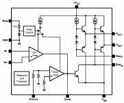
This is LME49830 diagram from appliction note.
I wonder why in every schematic, comprising appliction notes ones and also members proposals, we never see any resistor between N out and P out.
Meaning the driver stage inside the chip sees only the mosfet gates as load.
Should'nt it be beneficial to load this driver stage with some resistor as it can be seen in many mosfets amplifier schematics.
Edit: sorry i should have posted in the chipamp section.
Attachments
Last edited:
The resistor is optional; in the reference design from AN-1850, it is provided for but not installed. In a "normal" amplifier, the current flowing through that resistor biases the output stage. LME49830 has a different biasing mechanism, so the resistor (or rather Vbe multiplier) is connected to BIAS+ and BIAS- pins. There is no benefit in loading the driver stage AFAIK.
Yes, when Vas is directly connected to output mosfets.
Though, when a driver stage is implemented, there is usually a resistor (some hundreds ohms) between drivers emmiters. (Same position as the speed up resistor in a BJT darlington.)
In our case, drivers are inside the chip and bias circuit is in front of them.
NB:I must say i am not very familiar with mosfets.
I forgot this one. Though very high value and after gate stoppers.Are my eyes mistaking me, or is that not Rq =12k in Figure 1 of the datasheet?
Disapeared in AN1850 anyway as mentionned by Alexcp.
Looking more deeply at the chip topology, which is unconventionnal, i do understand how it works now. The driver stage is made of two independent N and P bridged outputs. That way it becomes unnessecary for a quiescent current to run between them; so no resistor is needed.
In a conventional driver stage a resistor is needed as quiescent current cannot pass through mosfets gates.
In a conventional driver stage a resistor is needed as quiescent current cannot pass through mosfets gates.
LME49830 has a higher DC bias range for the output stage (Nout - Pout) of 16 volts so that it can drive MOSFETS, whereas LME4910 is only designed to drive BJTs in darlington (about 3 volts).I am wrong as per datasheet voltage swing is almost the same as 49810-nearly the rails-
I still asking myself what this chip has special compared to 49810.
Looks like 49810 is able to drive mosfets as well.
Why did they built two different chips?
Did you find these LME49810 values by measurements/trials ?
Comparing datasheets they don’t look so different. (which btw isn’t so easy as not given the same way)
Lme49810
Bias Adjust Function Current : 2.8 mA
VBA Bias P&M Pin (Open Voltage BiasP – BiasM) : 10 V
LME49830
I AB Bias Control Current Shorted output, shorted bias control 2mA (1.6 mA (min) / 2.7 mA (max))
VBIAS Bias Voltage 16V
No. I did see LME49810 has 10V max bias spread in the data sheet, so its not much less than 16V on the '830. Maybe the '830 can be used in all designs where the '810 can be used, but not vice versa.Did you find these LME49810 values by measurements/trials ?
BTW, I have some info on my web site http://home.pacific.net.au/~gnb/audio/lme49810.html
Last edited:
Yourself say 49810 is ok for driving mosfets. (Read on your site which i already knew.)
8v should be enough which is less than 10.
I have built several bjt amps based on 49810 and also recently one based on 49830 feeding 2sk 1530/2sj201. I must say they sound identically.(not woth to spend that money on Toshibas)
I am posting in the hope of learning more about these chips.
I liked the article about audio myths.
Last edited:
- Status
- This old topic is closed. If you want to reopen this topic, contact a moderator using the "Report Post" button.
- Home
- Amplifiers
- Solid State
- LME49830 question