So ever since OPC introduced me to the LME amplifier chips I have wanted to make an amp based on them. Unfortunately I was unable to buy the boards he offered and so have designed my own. They work and feature a better heatsink for the LME.
There's an option to run the LME and output stage on separate rails.
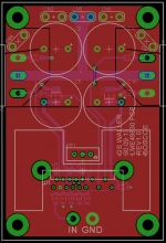
Here's some pictures and specs...


Blue line is 1W,
Green line is 50W
Both were run into 4R, 80KHz bandwidth, 35V rails (LME on the same rail) and at 300mA bias current. This is just with initial component values, I expect to get better performance once I have fiddled and run the LME on higher regulated rails.


You don't have to use an SMA connector for the input there are just holes there.
If anyone is interested in boards I will get some made. I have had a quick look at prices and for an order of 50 boards I will have to sell them at US$15+postage.
Last time I posted there were a few people interested so to get an idea of a number post your name and the names previous in your post with the number you want.
Thanks
Boscoe
There's an option to run the LME and output stage on separate rails.
Here's some pictures and specs...
Blue line is 1W,
Green line is 50W
Both were run into 4R, 80KHz bandwidth, 35V rails (LME on the same rail) and at 300mA bias current. This is just with initial component values, I expect to get better performance once I have fiddled and run the LME on higher regulated rails.
You don't have to use an SMA connector for the input there are just holes there.
If anyone is interested in boards I will get some made. I have had a quick look at prices and for an order of 50 boards I will have to sell them at US$15+postage.
Last time I posted there were a few people interested so to get an idea of a number post your name and the names previous in your post with the number you want.
Thanks
Boscoe
A big heatsink. Well done.
What about HF decoupling across the drains of the output devices?
What about HF decoupling across the drains of the output devices?
Last edited:
A big heatsink. Well done.
What about HF decoupling across the drains of the output devices?
Nothing on the current revision of boards I will add some and see what happens, no ill affects due to the lack of them yet.
I realize that it is a OPC clone, but what if by accident, you get a short on the load side? What protection measures are you incorporating or is this different discussion all together?
Blow a fuse all the way back to the mains fuse?
10uF/50V/1206 COG, bias cap, I bet that ain't cheap. Why 50V? I wonder if you use a X7R, would it make a difference?
I know Bob C. suggested in his book a optional R-C snubber, across the MOSFET Gate Drain?
Gate Zeners? Optional TPC?
Diodes across Drain/Sources?
Just some suggestions.
Rick
I realize that it is a OPC clone, but what if by accident, you get a short on the load side? What protection measures are you incorporating or is this different discussion all together?
Blow a fuse all the way back to the mains fuse?
10uF/50V/1206 COG, bias cap, I bet that ain't cheap. Why 50V? I wonder if you use a X7R, would it make a difference?
I know Bob C. suggested in his book a optional R-C snubber, across the MOSFET Gate Drain?
Gate Zeners? Optional TPC?
Diodes across Drain/Sources?
Just some suggestions.
Rick
It's not an OPC clone otherwise the board would be a lot like The Wire. The schematic is kept simple which makes it similar to OPC's design.
Use fuses on the outputs of you PSU or output protection off the board.
The bias cap is 100nF 50v NP0/C0G.
I don't think gate zeners are necessary. I haven't really got space for diodes across the outputs!
The National Semi prototype boards (for the 2SK1530/2SJ201) are showing up on EBay -- I've found that once an item starts trafficking they come out of the woodwork:
Should be easy enough to use with lateral mosfets by rearranging the pinout, or the readily available IRFP or Fairchild devices.
An externally hosted image should be here but it was not working when we last tested it.
Should be easy enough to use with lateral mosfets by rearranging the pinout, or the readily available IRFP or Fairchild devices.
Nothing?
might have something to do with Owen having updated 4 layer boards for sale again right now 😉
Hi guys I hate to drag this thread up but I've had a bit of interest in PCBs lately so I may knock something up.
PS. After a bit of refinement I managed 0.0008% THD+N with the board above at 1KHz, 10W, 8R and 80KHz bandwidth.
PS. After a bit of refinement I managed 0.0008% THD+N with the board above at 1KHz, 10W, 8R and 80KHz bandwidth.
Hi Boscoe,
I'm still interested (4 PCB's).
Nice distortion figure. How much distortion at higher frequency? 10K 20K...
I'm still interested (4 PCB's).
Nice distortion figure. How much distortion at higher frequency? 10K 20K...
Hi Boscoe,
I'm still interested (4 PCB's).
Nice distortion figure. How much distortion at higher frequency? 10K 20K...
Okay nice. I think 20K was around 0.0085%. That could be made better still with two pole comp.
Last edited:
That's even more impressive.
I have LME's and mosfets just waiting for your PCB 😉
Have you always been waiting!?
Have you always been waiting!?
Not always. I just happen to have good supply of LME's and MOSFET's to put into good use.
I couldn't find the original file so I drew another PCB.

Let me know if there's anything obvious wrong and I'll try and get them sent out tomorrow for a 3 week turn around. Unless there's a lot more interest I will be getting just 10 boards.
Let me know if there's anything obvious wrong and I'll try and get them sent out tomorrow for a 3 week turn around. Unless there's a lot more interest I will be getting just 10 boards.
Oh, I thought the layout was finalized - fixed. Now we have a new PCB layout.
My immediate response is like this:
Ground plane partitioning between high - low currents. High decoupling current directed through cap pins. And how about implementing gate zener protection?
My immediate response is like this:
Ground plane partitioning between high - low currents. High decoupling current directed through cap pins. And how about implementing gate zener protection?
Attachments
- Status
- Not open for further replies.
- Home
- Amplifiers
- Solid State
- LME49830 Project/Boards...