Dear,
Just a question.
The LME49810 has a (typ) output current capacity of 60mA. In almost all cases you need a driver transistor with a descent Beta to make a power amplifier. As exception here the STD03 darlingtons which have a hFE of at least 5000 and even more by higher currents.
Does this means I can theoretical parallel as many as STD03's as I want since output current seems endless?
0,060*5000= 300pkA. Let's say I want to stack 12 pairs of STD03's would this be possible?
With kind regards,
Bas
yes but you need to add resistors so that the Ib current distributes equally over the parrallel transistors.
enzoR said:yes but you need to add resistors so that the Ib current distributes equally over the parrallel transistors.
Thank you enzoR.
I was thinking about a value between 47 and 150 Ohm.
With kind regards,
Bas
Each Darlington pair needs it's own 200 ohm potentiometer...and you will probably have to experiment with the resistor across the bias pins to set the current across the diodes at 2.5mA.
jackinnj said:Each Darlington pair needs it's own 200 ohm potentiometer...and you will probably have to experiment with the resistor across the bias pins to set the current across the diodes at 2.5mA.
Dear Jackinnj,
Thanks for responding. Yes that is the next concern. 12 bias pot's is not fun...
However I saw in Musical Fidelity and Arcam design that they just tied all diode strings together to one pot. I don't believe this gives the best sound solution since there will be always differences between hFE's
With kind regards,
Bas
Sebastiaan said:
Dear Jackinnj,
Thanks for responding. Yes that is the next concern. 12 bias pot's is not fun...
However I saw in Musical Fidelity and Arcam design that they just tied all diode strings together to one pot. I don't believe this gives the best sound solution since there will be always differences between hFE's
With kind regards,
Bas
Ask Janneman -- he used individual bias pots in his PAX amplifier -- (Elektor April 08) and Sanken recommends the same thing...I believe it is due to the possilibity that the betas of the Darlington's might not be the same.
jackinnj said:
Ask Janneman -- he used individual bias pots in his PAX amplifier -- (Elektor April 08) and Sanken recommends the same thing...I believe it is due to the possilibity that the betas of the Darlington's might not be the same.
Dear jackinnj,
I am agree with you and Jan that this is the best way. Also Sanken's application sheet advice a pot per pair.
However, this is how Arcam does it.
With kind regards,
Bas
Attachments
Dear All!
I want to buy an amplifier with LME489xx driver one or two pair SAP15s. What LME chip I will choose? LME49810 or 49811?
Thanks.
I want to buy an amplifier with LME489xx driver one or two pair SAP15s. What LME chip I will choose? LME49810 or 49811?
Thanks.
I am currently working on a project with SAP15s and LME49811. I think 49811 is the best solution for SAPs. Because they already have a biasing systems and do not need Vbe multipliers. So if you consider 49810 and 49830 has bias pins then 49811 (or LM4702) is the best for SAPs. Another point is 49811 has Class A driving stages..
Dxvideo,
I'm working on the same thing. Can you post your schematic? have you mocked it up yet?
Ken
I'm working on the same thing. Can you post your schematic? have you mocked it up yet?
Ken
An externally hosted image should be here but it was not working when we last tested it.
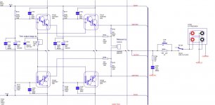
Dear Ken,
This is my application schematic. However PCBs are still in manufacturer. I am expecting to finish my amp in next week. So I will report the results after the first tests...
Sebastiaan said:
Dear jackinnj,
I am agree with you and Jan that this is the best way. Also Sanken's application sheet advice a pot per pair.
However, this is how Arcam does it.
With kind regards,
Bas
The ARCAM way (one pot for 2 pairs) has the real risk that each pair has a different bias current, or even guarantee it, unless you match the output devivces, and I doubt they did that (it's expensive in a production environment).
So you probably have one pair that gets hot and another stays cold, and I don't know what the different bias does to the xover distortion. I would use a separate pot for each pair.
Jan Didden
Dxvideo said:An externally hosted image should be here but it was not working when we last tested it.
Dear Ken,
This is my application schematic. However PCBs are still in manufacturer. I am expecting to finish my amp in next week. So I will report the results after the first tests...
What is the Isink and Isource from that 49811? Sanken specifies 2.5mA per diode string for best thermal tracking.
Jan Didden
9ma is the limit for LME49811 for both sinking and sourcing.. In my configuration, I will measure the Ibb and will set it up to 2.5mA.. I expect to have a good bias level with this Ibb..
Dxvideo said:9ma is the limit for LME49811 for both sinking and sourcing.. In my configuration, I will measure the Ibb and will set it up to 2.5mA.. I expect to have a good bias level with this Ibb..
What's Ibb?
Jan Didden
Dxvideo said:Ibb is I base to base... The current on thermal tracing diodes..
OK, then you set that to 2.5mA, and then you set the pot for 40-60mA in the output devices. Sanken recommends 40mA, but I use 60mA which gives slightly less xover distortion and still good thermal tracking.
Jan Didden
Dxvideo said:Have you ever tried extreme high bias levels that more close to class A (like 1A!!!)
No I haven't. You would need better heasinking of course and I'm not sure how the thermal tracking would keep up, to avoid thermal runaway.
I also don't expect it to give better sound.
Jan Didden
I am agree with you about the sound quality with more bias..
Just I'd like to try, but I am afraiding to destroy the diodes, because Sanken gives 2.5ma for the maximum Ibb level.. Anyway, I guess it would be better to keep it at 40mA bias (or 60 like yours)..
What about the sound quality of your amp? Have you ever compare it with a gainclone or a good discrete amp?
- Status
- Not open for further replies.
- Home
- Amplifiers
- Chip Amps
- LME49810/STD03 parallel pairs