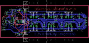
Hello DIY'ers,
I've finally made my first try-out pcb for the LME49810. I tried just to apply 26-28 Volt to the board to check if everything was working out. But when I apply the supply I can read >20 Amps are being drawn from the supply (2 screw driver batteries). I don't know what's wrong. I've posted my schematic and I can take some voltage measures on different spots on the pcb if you need it. Nothing is burning out. I only recognize some heat from the output transistors, so I guess the problem lays there. Also when I connect a speaker it just make a little pop noise.
Regards,
Simon H.A.
Attachments
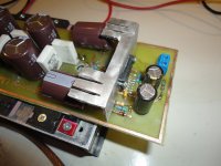

Did you check if all transistors are isolated from the heatsink?
I'm intrested in making an amplifier with the same chip. Could you post a schematic, not a layout?
I'm intrested in making an amplifier with the same chip. Could you post a schematic, not a layout?
Sorry for the late response, was away for a momement. Yes I've done a lot in making sure none of the transistors are short cutting each other on the heat sink. I bought some good heat pads @ Digi-Key.
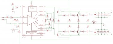
Here is my schematic used for this board.
Edit: The potentiometer is 200 ohm 😉
Here is my schematic used for this board.
Edit: The potentiometer is 200 ohm 😉
Attachments
Last edited:
you're having some obivious mistakes in the design.
you're using multiple transistors in the output but do not have current sharing resistors, so one of the transistors in the output will end up doing all the work the rest will be just sitting there.
You need to have a Zobel on the output of your amp.
A small film cap like 0.1 uf across the collector and emitter of the Vbe multiplier is required.
If your POT is 200ohms then 1.2/(300 + 200 ) > 2 even when the pot is at it's full resistance you'll still be having a good amount of bias, instead use a 680 + 500 ohm pot
Last edited:
Hi Sasmit,
The schematic and the PCB has 0.22 ohm current sharing resistors from emitters to ground. Yeah this amp might be oscillating hence drawing lots of current.
CyberZim,
Disconnect the power transistors and leave the driver transistors and check the voltages. For temporary testing, also break the emitter resistor on the driver transistors into two equal values and take the feedback from these resistors. This setup will allow you to measure DC voltages without burning power outputs. The emitters of these driver transistors should have +0.6v and -0.6v (or even less) then you'll have an idea whether there are any faults in the layout.
If the voltages are good and large currents are drawn after connecting the power transistors back, check for oscillation. A zobel network help suppress the oscillations.
Thanks,
Routhun
The voltage gain of the circuit is 150 (Rf/Rin) and is way too high for the 10p compensation cap. Cc should be silver mica by the way, not a Z5U chip ceramic. Recommended values are gain 30 (Rf = 6k8) and Cc 30p.
Therefore suspect your circuit is oscillating - hence the high current drain.
Query if the wiper of the pot is open circuit (it is on your schematic).
Cheers
Therefore suspect your circuit is oscillating - hence the high current drain.
Query if the wiper of the pot is open circuit (it is on your schematic).
Cheers
Okay, as far as I understand I have to do the following changes:
Replace potentiometer with a 500 ohm pot.
Also replace the 300 ohm resistor in the bias connection with a 680 ohm.
Replace Rf with 6k8 ohm.
Also when I have to test for the voltages I've added a schematic with all the things I think I understand what to do.
Replace potentiometer with a 500 ohm pot.
Also replace the 300 ohm resistor in the bias connection with a 680 ohm.
Replace Rf with 6k8 ohm.
Also when I have to test for the voltages I've added a schematic with all the things I think I understand what to do.
Attachments

do not connect a speaker until AFTER you have proved that the amplifier is working correctly for all conditions.
I've changed the components and also cutted the power transistor off from the drivers. I get a -0,7 volt on the npn driver and 0,7 on the pnp driver transistor.
CyberZim,
I guess you should have +ve voltage on npn driver and -ve voltage on pnp driver, what you have reported is opposite please check the voltages again. Also 0.7v at the emitters of the driver is a bit high and adjust the bias pot to see if this voltage goes down to 0.5v or so. You can latter adjust this based on the quiescent current on the outputs.
Thanks,
Routhun
Oh, it was the emitter pin :O... What should I use as a referee when measuring? GND?
Edit: When I use ground as referee with my multimeter I get -35V on PNP and +39V on NPN @ +/- 38 V... something is really wrong :S
Edit: When I use ground as referee with my multimeter I get -35V on PNP and +39V on NPN @ +/- 38 V... something is really wrong :S
Last edited:
Did you remove R13? if so please connect it back. What I mean to say in my earlier post is to break it into 2 different resistors, each of 90ohms and connect the mid point of it to the feedback.
Also check the bases of driver transistors? they should be around +1.2v (NPN) -1.2v (PNP). If the voltages are higher than this, check for if the VBE multiplier transistor is open or correctly connected.
Let us do more debugging before suspecting the chip.
Thanks,
Routhun
Also check the bases of driver transistors? they should be around +1.2v (NPN) -1.2v (PNP). If the voltages are higher than this, check for if the VBE multiplier transistor is open or correctly connected.
Let us do more debugging before suspecting the chip.
Thanks,
Routhun
I cannot take the R13 and divide it into to 90 ohms resistor and connect it to the feedback because with +/- 38 V the current is so high that they start to burn.
The base voltage on the pnp is -32V and +39V on the npn driver transistors base (ground as COM on multimeter).
I've checked and the VBE multiplier transistors are connected correctly to the LME49810.
Regards,
Simon H.A.
The base voltage on the pnp is -32V and +39V on the npn driver transistors base (ground as COM on multimeter).
I've checked and the VBE multiplier transistors are connected correctly to the LME49810.
Regards,
Simon H.A.
May be chip got toasted 🙁 these voltages should not be that much high and it cause destruction of outputs. As a final attempt, check the driver transistors and make sure they are not shorted. Remove them from the PCB and check with the multimeter.
Thanks,
Rao
Thanks,
Rao
I think it's the chip that's dead. I will create a new and better pcb because I've got my failures fixed with the design and then try again with fresh components. If you have any suggestion to my schematic (beside that the bias potentiometer is wrong connected 😀) then I would pleased to hear from you before I begin with the redesign. I've actually learned a lot in the design of this type amplifier which is the only positive thing to say 🙂
Regards,
Simon H.A.
Regards,
Simon H.A.
- Status
- Not open for further replies.
- Home
- Amplifiers
- Chip Amps
- LME49810 pcb layout - Troubles