Hey that runoffgroove site is fantastic!
As for that circuit could I don't have such a transistor, so.. 🙂 then again, could i substitute that part with a simple inv amp built with a 741 (I happen to have many)?
If its not good please I'm very interested to understand the reasons
Thanks everyone for bearing with my crazy questions, I do appreciate your answers and patience 🙂
thanks for the pointers guys! I've been using op amps to amplify small signals and feed them into a scope but never drove a speaker, this was my first naive attempt.
So the 741 is bad because of its high output impedance and low output current... if I stack one 741 on top of another wouldn't I get double output current and half output impedance?
gaetan: So what makes an opamp a good candidate for audio? Just output current and low output impedance?
"Stacking" opamps... have a look at this (link in first post). So yes it can be done but you need a lot to make it worthwhile.
http://www.diyaudio.com/forums/chip-amps/174540-doug-selfs-ne5532-power-amp-thoughts-anyone.html
The term opamp generally refers to low power devices. There are dedicated "power opamps" that have a huge following. Check out the "Chip amp" forum on here.
Chip Amps - diyAudio
All you need for your 741 is add a couple of high gain transistors and a simple bias network to drive a speaker... great for learning.
All you need for your 741 is add a couple of high gain transistors and a simple bias network to drive a speaker... great for learning.

hehe, I'm glad that the idea of stacking amps was not that crazy 🙂
So do you think I could use a couple of 2n2222 after the 741 to drive a speaker?
I'll try to get a nice biasing and try it out in the simulator, the whole point is to learn!
So do you think I could use a couple of 2n2222 after the 741 to drive a speaker?
I'll try to get a nice biasing and try it out in the simulator, the whole point is to learn!
Just a question regarding the use of ua741 in a power supply, would the modern versions like lm471 be less noisy, or superior to the ones form the 80's?
hehe, I'm glad that the idea of stacking amps was not that crazy 🙂
So do you think I could use a couple of 2n2222 after the 741 to drive a speaker?
I'll try to get a nice biasing and try it out in the simulator, the whole point is to learn!
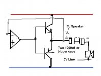
This is the starting point... an NPN and PNP power transistor such as a TIP41 and TIP42
The output of the opamp goes to the transistor bases as shown.
Whatever feedback nework you had connected to pin 6 (opamp output) now moves to the emitters of the transistors.
With any DC coupled amp like this and particularly as you are learning it's imperative that the speaker be protected. That means checking the output of the amp is at zero volts DC with no signal and perhaps adding a couple of back to back electroylitics to prevent damage if a fault or mishap occurs.
Edit... the grey line is the feedback network, missed the resistor out drawing it 🙂
Attachments
digits: likely they are better quality but whether you will see that on the output depends a lot on the circuit topology and layout.
Thanks, I want to upgrade my signal generator, which is quite old and has lots of old IC's from back in the day when I was at school in the 80's and early nineties.
thanks for the pointers guys! I've been using op amps to amplify small signals and feed them into a scope but never drove a speaker, this was my first naive attempt.
So the 741 is bad because of its high output impedance and low output current... if I stack one 741 on top of another wouldn't I get double output current and half output impedance?
gaetan: So what makes an opamp a good candidate for audio? Just output current and low output impedance?
Hello xchip
The741 are bad also because it have a very low slew rate of .5 v/us , that's too slow and it cause slew induced distortions, and that opamp do have a low gain bandwidth.
A good opamp should have a low thd, a good gain bandwidth and a high slew rate, the LM5532 and LM5534 do have arround a slew rate of 9 v/us
Bye
Gaetan
Last edited:
@Mooly, hey, looks smple and nice! and such a simple network guarantees me that the transistor are biased the right way?
I am using Circuit Simulator Applet just to bias a single transistor and I am really sweating it!
@gaetan: Wow! And I thought that .5v/us would be a lot for audio! I guess that is a problem with high voltages..
Thanks!
I am using Circuit Simulator Applet just to bias a single transistor and I am really sweating it!
@gaetan: Wow! And I thought that .5v/us would be a lot for audio! I guess that is a problem with high voltages..
Thanks!
20V/us to 50V/us slew is generally thought adequate for a 100W amplifier feeding an 8ohm speaker. You will find very few manufacturers quoting <20V/us but some might state >=15V/us.
If you have good floating or battery supply you can always drive the emitters into ground or 1/2VCC with a capacitor coupled output from the supply common. Helps reduce slewing demands on the input amplifier.
Hi!
I just implemented what Mooly suggested, you can check it out in this Circuit Simulator Applet.
Some thoughts:
1) It seems I don't need any resistor biasing network, probably because one is in cutoff the other is in the active zone and viceversa. Also I didnt notive the zero cross distortion
2) I am surprised that even the gain is only 12, given that the op amp gain is 100. Any ideas why?
3) Also the speaker, represented by a 8hom resistor is consuming only 20uW... isn't that too low?
I feel I am making some little progress, wohoo! 🙂
Thanks!
Last edited:
Guitar amps are funny beasts. The amp and speaker usually add some sort of distortion to create an instrument that is different from the typical "clean" Hi-fi amp. The low slew rate of the 741 may add a distortion that you like, it may not. If you put it in a socket, you can swap out op-amps and try different ones. Also, rather than building with discrete transisitors you may want to try a power op-amp. Feed the output of your 741 into a LM4950 to get a few watts of power, enough to drive a speaker to acceptable volume. The 4950 is very easy to use, it's just a higher powered opamp that's been optimized for audio use (not hi-fi, but at least mid-fi quality). Read the datasheet http://www.national.com/ds/LM/LM4950.pdf for details on how to use it, it's dead simple and cheap.
Thanks! I'm not worried too much about the quality at this point since the whole point of this is to learn. Once I get the basics I'll start improving it.
Last edited:
Hi!
I just implemented what Mooly suggested, you can check it out in this Circuit Simulator Applet.
Some thoughts:
1) It seems I don't need any resistor biasing network, probably because one is in cutoff the other is in the active zone and viceversa. Also I didnt notive the zero cross distortion
2) I am surprised that even the gain is only 12, given that the op amp gain is 100. Any ideas why?
3) Also the speaker, represented by a 8hom resistor is consuming only 20uW... isn't that too low?
I feel I am making some little progress, wohoo! 🙂
Thanks!
1. The circuit as drawn is OK, however the 10uf cap needs to be increased to at least 1000uf for the circuit to have a decent low frequency response into 8 ohms. Crossover distortion will be obvious at low levels.
2. I can't figure the simulator result out... I tried altering levels with no success. As drawn the circuit definitely has a gain of 100 at low to mid frequencies.
Both in practice and in the simulator I would use higher supplies. -/+5 isn't much. Use -/+12
I was just looking back at some of the other posts and post #7 by CBS240 shows what would be the basis of the next stage, but you need to get this working first.
My preamp is working fine, when I plug the guitar for some reason I could hear The Beatles playing, at first I thought my guitar was haunted, but then I realized it was some radio station.
It's happening quite consistently and not sure how to get rid of it... any ideas? Thanks!
It's happening quite consistently and not sure how to get rid of it... any ideas? Thanks!
- Status
- Not open for further replies.
- Home
- Amplifiers
- Solid State
- LM741 :-)