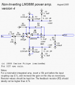
When building PCBs for my 4 channel amp based on parallel configuration of LM4780 chips and Carlosfm’ NI LM3886 amp version 4 schematic I have encountered a circuit problem related with mentioned schematic and placement of additional components needed to configure the amp to function in parallel configuration. These are 0.1 Ohm output resistors, connected between each other. So, when I build a PCBs and soldered needed components I measure resistance with my DMM between Output path and -IN path of PCB at chip pinout. This is where gain setting resistors are located (R3 in that schematic (Rf - according to National schematics). Than I found that resistance was 1,045kOhm, when needed value is 2KOhm. This is because of gain setting resistors are connected between each other via feedback resistors (R2 (Ri - according to National schematics) which are also connected between each other through Ground (because of without feedback capacitors). R2 (Ri - according to National schematics) resistors show 98Ohm, when needed value is 100Ohm.
In other words, around every gain setting resistor (R3(Rf) there is the circuit which is formed by feedback (R2(Ri) and output (Rout) resistors and change the gain setting resistance from 2KOhm to 1.045kOhm. The same is with feedback resistors (R2(Ri) - from 100Ohm to 98Ohm. When there are feedback capacitors are present (Ci) this is not happening.
Therefore I guess this configuration is unacceptable for chips. However, the situation would be different with feedback capacitors, but they must be very big ones what is unacceptable too.
What do you think guys? Am I wrong about the problem and all is normal and correct. If I'm not wrong than is this possible to build the parallel configuration based on LM4780 chip without feedback capacitors?
Many thanks for your help.
Attachments
All is normal and correct. You are getting the wrong values, because the way you apply voltage during your measurements is different from the way voltage is applied during operation.AndriyOL said:What do you think guys? Am I wrong about the problem and all is normal and correct.
Thanks for your answer.
My way of measurement is not wrong because what is important this is the impedance between output and -IN pins of IC I suppose. If I would place a feedback cap the impedance will be different and right.
My way of measurement is not wrong because what is important this is the impedance between output and -IN pins of IC I suppose. If I would place a feedback cap the impedance will be different and right.
No, it is not wrong. It is only meaningless.AndriyOL said:My way of measurement is not wrong
When you measure a resistance, you put a kown resistor in series, put a voltage across both and measure the voltage drop across the unknown resistance. In your first post you pointed out that you are also measuring everything that is connected in parallel to the resistor you are measuring, thus do not get the correct value. You got that absolutely right.
When the amplifier operates however, the voltage source is not across each resistor, but across the output terminals. You could simulate that by putting a low voltage across the speaker terminals (amplifier off and speaker disconnected of course) and measure the voltage drop at the inverting input. You will see that it is proportional to the resistors, even without Ci.
No, there is a circuit and output resistors, gain setting resistors and feedback resistors are connected in series which form a circuit. It can be seen at parallel schematic of LM4780 datasheet when imaging that feedback caps are omitted and ground of feedback resistors are connected together. Applied voltage goes where the lowest resistance is. When feedback cap is present in the amp the lowest resistance is gain setting resistor (2K) because there is no circuit. When it omitted the lowest resistance is other side of the circuit or other part where gain setting resistor is located.
BTW, in parallel configuration of LM4780 without Ci caps inverting inputs are shorted through feedback resistors.
BTW, in parallel configuration of LM4780 without Ci caps inverting inputs are shorted through feedback resistors.
AndriyOL said:No, there is a circuit and output resistors, gain setting resistors and feedback resistors are connected in series which form a circuit.
Once your power supply is connected those will be different circuits in parallel. Ground is the return path for all of them.
AndriyOL said:It can be seen at parallel schematic of LM4780 datasheet when imaging that feedback caps are omitted and ground of feedback resistors are connected together.
Then the current flows from the output through the resistors into the ground and back to the power supply.
AndriyOL said:Applied voltage goes where the lowest resistance is.
The voltage is present everywhere. The current is divided according to where the lowest resistance is.
AndriyOL said:When feedback cap is present in the amp the lowest resistance is gain setting resistor (2K) because there is no circuit.
Yes, there is a circuit. Your multimeter works with DC, and a capacitor blocks DC. That is why your measurements are different with or without capacitor.
For the AC signal that will be present, when you play music through that amplifier the capacitors will only make a difference at low frequencies. At audio frequencies there will be none.
AndriyOL said:BTW, in parallel configuration of LM4780 without Ci caps inverting inputs are shorted through feedback resistors.
They are not shorted, because the ground is the return path for those signals. Don't get confused with the power supply. Imagine the split power supply as two single supplies. One part is from plus to ground and works for the positive half cycle, the other is from ground to minus and works for the negative half cycle. Then follow the signals again for each half cycle, i. e. as if only one of the two power supplies were present at each time. Or to make it more visual, cover V- and see, where the curent flows. Then uncover V- again, cover V+ and see, where the current flows.
Ok. You convinced me. Maybe I was wrong.
I'll try to power it and tell you results.
Many thanks for your help.
I'll try to power it and tell you results.
Many thanks for your help.
Hi, pacificblue.
The amp is not working. Chips are drawing much current (because toroid humming like never in normal use) and speakers reproduce only hum (like radio signal). Inputs disconnected. I can’t imagine where the problem is.
Could you help me?
The amp is not working. Chips are drawing much current (because toroid humming like never in normal use) and speakers reproduce only hum (like radio signal). Inputs disconnected. I can’t imagine where the problem is.
Could you help me?
Can you post the layout or good photos of everything?
Did you check the power supply without amplifier connected?
Is there hum with something connected to the input? And with an input signal?
Do you use a lightbulb tester? Or a limiting resistor in place of the fuses?
Did you check the power supply without amplifier connected?
Is there hum with something connected to the input? And with an input signal?
Do you use a lightbulb tester? Or a limiting resistor in place of the fuses?
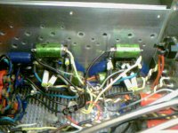
Here are some photos. Sorry, poor quality I have camera only in cell phone. Layout is like in pdf file added but with other values of resistors which are according to carlosfm schematic. This is a rebuild version of amp. I already had it working under National parallel schematic. When I designed it according to National schematics without PCBs it worked pretty well, however with low frequency distortion on lower power (lower loud) levels in some cases (when there is low frequency buzz reproduction). Than I redesigned it in accordance with carlosfm LM3886 schematic with PCBs.
Till I try only two channels with carlosfm schematics and with one PSU. Have 4 channels, 2 PSUs.
PS rails of chips I make with cooper wire (1.3mm) – “- V” is on left “+V” is on right of the chip. Mute and Ground from the chip are also with wire. PCB is for “OutA” – ”-INA” – “+INA” – “-INB” – “+INB” – “OutB” traces only. Star ground also is with wires. Signal ground is on PCB which formed by Ri, Rin resistors, source ground, than direct wire without RG resistor to star ground. Before, when I placed RG resistor the distortion was becoming worse. So, I disconnected it.
All resistors are correct. I already checked and rechecked. All is fine and like it should be, I guess. I measured all and nothing is shorting.
PSU is working well with amp disconnected with 1 or 2mV difference between voltage rails. I have 300 or 400VA transformers custom wired by myself (only secondaries). I don’t exactly know how to measure VA ratings. I use 2A 250V fast blowing fuses. 1.6A were blowing up during start up from time to time. 2A value is Ok.
Maybe the problem is caused by 3.3uF MKP cap placed between voltage rails regardless to Ground. I never used it before. Or low input impedance (330Ohm) and amp is oscillating?
I don’t have a lightbulb tester or limiting resistor (I don’t know what they are). Fuses are Ok.
I didn’t try to connect to amp any input source yet as it’s not working. It worked well before without input source connected and any hiss or hum.
However, once I tried to use it without feedback caps – feedback resistors (Ri) directly to Signal ground, because one diyaudio member (dxvideo maybe) claimed that without Ci cap amp worked just fantastic.
As a result I had 0,5V on speakers’ outputs and distortion instead of low frequency reproduction, but without that hum what is now with no inputs connected.
My design of entire amp on photos is pretty fun.
Attachments
I can't post all photos. Limitation on forum is to 102400 bytes.
If you want I can send it you by email.
If you want I can send it you by email.
Are you aware of the SPiKe protection system? That interrupts the rails in case of clipping, which results in a buzzing sound. Something that happens most of the time, when bass notes are reproduced. Possible cures areAndriyOL said:it worked pretty well, however with low frequency distortion on lower power (lower loud) levels in some cases (when there is low frequency buzz reproduction).
- - increase or stabilize the rail voltage.
- reduce the volume
- reduce equalizing, if you have some.
- use more efficient speakers.
You should rather look for the capacitors, especially the electrolytics. Are they connected in the right direction? Are their connections in order? Resolder them, if you can, just to be sure.AndriyOL said:All resistors are correct. I already checked and rechecked.
And how high is the rail voltage actually?AndriyOL said:PSU is working well with amp disconnected with 1 or 2mV difference between voltage rails. I have 300 or 400VA transformers custom wired by myself (only secondaries).
No.AndriyOL said:Maybe the problem is caused by 3.3uF MKP cap placed between voltage rails regardless to Ground.
No.AndriyOL said:Or low input impedance (330Ohm)
Maybe, but not likely, if you used Rz and Cz like in the schematic.AndriyOL said:and amp is oscillating?
A light bulb tester means that you connect a light bulb in series with the transformer primary. If the current is low, the bulb will be off and the amplifier will work. If the current is high, e. g. due to a short circuit, the bulb will light up and the current is limited. You have to experiment with the light bulb size until you find the right balance between working under normal condition and stopped at fault. Once you have that, it allows you to measure the working amplifier without destroying it.AndriyOL said:I don’t have a lightbulb tester or limiting resistor (I don’t know what they are).
A limiting resistor is used instead of a fuse. It also limits the current in case of a mistake, but it also does that, when there is no mistake, so it is not as comfortable to use as a light bulb tester.
AndriyOL said:I didn’t try to connect to amp any input source yet as it’s not working. It worked well before without input source connected and any hiss or hum.
Amplifiers usually sound better without them, but they have less protection. The original Gaincard works without it and the V4 from CarlosFM also. If you had Ci in, then your layout is obviously different from the schematic. What else is different?AndriyOL said:However, once I tried to use it without feedback caps – feedback resistors (Ri) directly to Signal ground, because one diyaudio member (dxvideo maybe) claimed that without Ci cap amp worked just fantastic.
Did you put Ci back in? Is it possible that something happened, when you did that, that led to the fault? E. g. Ci connected the wrong way round? A wire torn off, which you haven't noticed? There seem to be two disconnected white wires in your photo. A bad connection somewhere due to a loose screw or a solder joint with a hidden defect? Bad solder joints often lead to hum, especially at the big electrolytics in the power supply.AndriyOL said:As a result I had 0,5V on speakers’ outputs and distortion instead of low frequency reproduction, but without that hum what is now with no inputs connected.
You can upload pictures to hosts, and then post a link to that. E. g. http://imageshack.us/ or http://photobucket.com/ or others. Google for picture hosting.AndriyOL said:I can't post all photos. Limitation on forum is to 102400 bytes.
If you want I can send it you by email.
I think it’s not SPiKe protection. I played the amp not more than 40% of volume level on my sound card (Audigy2ZS) which have 1Vrms output signal I guess (DMM shows 0,6-0,8mVDC), when needed value is 1,5Vrms. Heatsinks never heat more than 70C (Celsius) or 158F, so I can hold my hand on it. Distortion occurs in some music reproduction when there was some buzzing sound to reproduce. BTW, distortion became lower when AC Voltage was higher (from 220VAC to 240VAC), hence 35V DC became 39V DC without load (I have toroid with 2x25VAC secondaries). I guess the problem was related with Chinese PS caps (Samwha) on chip which ground traces were connected by one wire only for both of voltage rails of the chip to Star ground. Also it can be related with high capacitance component of speaker cables from the amp outputs (I have 5m long speaker cables 2.5mm D). Speakers are 93db of sensitivity. Suppose they are efficient.
All lytic caps are Ok: “+” pin of every cap to V+ rail of chips, “-“ pin to –V rail of chip, pins of caps are fixedly soldered.
Voltage rails are 35V +V-VDC.
I don’t use 10uF PS caps like before on voltage rails of chips.
I use Rz – 2R7 with non inductive windings resistors with Cz - 0.1uF 630V MKP caps. However before I tried to play amp without Zobels and there was no only high frequency response.
I never saw on my market bulb testers. What is its manufacturers and model number (if available). Can I make it by myself?
I had Ci before redesigning to carlosfm schematic and amp worked with National parallel schematic. Than I tried to use it without Ci cap and get constant without input source 0,5VDC on output with distortion instead of low frequency response with input source. Now I constructed the amp according to carlosfm schematic and it’s not working. I tried to power it up with carlosfm schematic 3 or 4 times with duration of 2-4 seconds.
Btw, inputs and outputs on the PCB are located from each other with approximately 50mm (0.164ft) of distance and input 2.2uF cap is soldered under output resistor with distance between pins of each other 10mm (0.033ft). Maybe this is causing the problem.
All grounds are connected independently to single star ground point. Except Zobels for every channel, grounds for every voltage rail have single wire.
I don’t have disconnected white wires. There are supply wires (black -V (left side of the chip) and yellow +V (right side of the chip) from the chip), others are ground wires to star ground. It’s PS grounds and snubber grounds. On big white caps on PCB is Zobel ground. White wires goes only from signal ground to star ground and less visible on photo.
About PCB. Input resistance is 15K. It’s on quasi-PCB and goes from input to signal ground. Input is located below of PCB where green 2.2uF cap is soldered, signal ground is above of the PCB which formed by 100Ohm feedback resistors and 15K input resistor than from signal ground direct wire to star ground.
Speaker is alive by which I tested the amp (other was 4Ohm wire). So, I suppose voltage on outputs was not big. Once, I burned a pair of speakers. It’s because the problem was with input resistance (Ri, R1). Now it’s not.
I have no bad connections or solder joints. Star ground is bolted to a chassis. If there were no big electrolytics there wouldn’t be any bass I guess.
I added the similar layout in pdf. Mine is same but with components according to carlosfm schematic plus output resistors.
All photos hosted at:
http://profile.imageshack.us/user/andriyol/
Attachments
If you use 4 Ohm speakers, 35 V rails are very high. You should not use more than 2x 18 V transformer with 4 Ohm loads. You probably have a temperature problem. With 35 V rails you get a maximum power dissipation of 128 W. The IC cannot dissipate more than 125 W at 25 °C junction temperature and must be derated for higher heatsink temperatures. The datasheet specifies 25 V rails for 4 Ohm loads.AndriyOL said:BTW, distortion became lower when AC Voltage was higher (from 220VAC to 240VAC), hence 35V DC became 39V DC without load (I have toroid with 2x25VAC secondaries).
It is only a light bulb. No manufacturers or model numbers. You have to make it yourself. Start with a small one, and step the power up until you have a value, with which your amplifier runs well, if there is no mistake. 60 W seems to be a commonly used value. It is a good idea to use it any time you make a change to your amplifier, just in case there is a malfunction or a short. For your current issue it will not help you, however.AndriyOL said:I never saw on my market bulb testers. What is its manufacturers and model number (if available). Can I make it by myself?
You didn't have the same problems with the parallel schematic, because in parallel operation you only have half the power dissipation per IC. Each amplifier channel only needs to drive half the load and works as if it was with 8 Ohm speakers.AndriyOL said:I had Ci before redesigning to carlosfm schematic and amp worked with National parallel schematic. Than I tried to use it without Ci cap and get constant without input source 0,5VDC on output with distortion instead of low frequency response with input source. Now I constructed the amp according to carlosfm schematic and it’s not working.
You could combine the parallel operation with the input filters and snubbers of CarlosFM's schematic to solve that issue, if you don't want to reduce the rail voltage.
In datasheet for parallel configuration +-35 rails voltage are used. I use parallel configuration also, but with components according to carlosfm' schematic plus output resistors. For IC it's like 8Ohm load on every amp inside. This is not a problem. I'm sure of that.
About bulb tester. Can I use simple 100W 220VAC domestic bulb. As I now IC quiescent power supply current is 170mA (max)*2 IC + 10mA supply current of my toroid = 77W (220VAC). Than 100W bulb should be right.
However, bulb will not limit the supply current if there is a short circuit? It's only light up?
As input filters you mean AD815?
But I guess the problem derives because inputs and outputs on the PCB are located from each other with approximately 50mm (0.164ft) of distance and input 2.2uF cap is soldered under output resistor with distance between pins of each other 10mm (0.033ft), which wasn't in my previous built version. As for me such placing is not acceptable for power amps. it's like self excitation. This can be seen on my photos.
I can't imagine what other can cause this problem. However, in datasheet it is called cross talk performance and recommended that input and
output traces must be separated by as much distance as possible.
What do you think about it?
If 60 W are okay for a single channel amplifier, 100 W will probably work for aparallel configuration.AndriyOL said:About bulb tester. Can I use simple 100W 220VAC domestic bulb.
Yes, it will limit the current. That is the point. A light bulb is an NTC resistor, i. e. when it is cold is has low resistance and little voltage drop across it. When high current flows through it, it will heat up, its resistance rises and voltage drops across it. Less voltage remains for the transformer and so the current is limited.AndriyOL said:However, bulb will not limit the supply current if there is a short circuit? It's only light up?
No, I was refering to the input filters in CarlosFM's schematic. In fact I was proposing that you make the amplifier exactly, like you already did, because I didn't know that you had already done thatAndriyOL said:As input filters you mean AD815?
50 mm should be sufficient. The capacitor and resistor could be an issue, however. If you can, try to separate them. 20 to 30 mm should already help. Or turn one of them by 90°, so that they are not parallel anymore.AndriyOL said:But I guess the problem derives because inputs and outputs on the PCB are located from each other with approximately 50mm (0.164ft) of distance and input 2.2uF cap is soldered under output resistor with distance between pins of each other 10mm (0.033ft), which wasn't in my previous built version. As for me such placing is not acceptable for power amps. it's like self excitation. This can be seen on my photos.
Hi, Pacificblue.
I have tried to do as you advised me. I soldered two wires to the bulb 220V 100W and connected the bulb in series to the primary of a toroid and than powered the amp constructed with separated input caps and output resistors and without 3.3uF caps on supply voltage rails.
As a result I noticed that bulb was light up but speakers worked quiet, so a DC offset is negligible. Than I measured DC offset on chips’ outputs. At first, on 1-st chip output I got 131-134mV DC offset, than I got 30-31mV and again the same. So, I cannot determine what value is right on 1-st chip. On second chip DC offset was 30-31mV. Another fact which I regard to be important was the amp worked intermittent. I mean that the bulb was light up and go out and same again. Maybe this was under voltage protection of chips because rails voltages of PSU were 10-12VDC.
Hence, I don’t know if the amp is Ok or there is a short circuit somewhere.
Could you advise me something.
Thanks.
AndriyOL said:I got 131-134mV DC offset
That is quite high. Did you terminate the input with a resistor, e. g. 100 Ohm, when you measured that?
If yes, do you have the possibility to insert Ci. That should bring the DC offset at the output down. For a test it can be something smaller, like 47 µF or so. For serious listening it should be 220 µF or higher with that small 100 Ohm Ri.
Another test could be to take Cs out, because that stores the DC offset voltage across the inputs.
Another possibility for such a fault with a parallel application could be that the feedback resistors are not matched. Ri and Rf should have 0,1 % tolerance to avoid the ICs battling each other.
AndriyOL said:Maybe this was under voltage protection of chips because rails voltages of PSU were 10-12VDC.
Either that or the muting current became too low. The undervoltage protection activates, when the negative rail is less than 9 V below ground or when the difference between positive and negative voltage is less than 14 V.
AndriyOL said:Hence, I don’t know if the amp is Ok or there is a short circuit somewhere.
If there was a short, it would probably switch off completely.
You could try to use a bigger light bulb or two in parallel. If possible increase them so that you can be sure that the undervoltage protection does not set in, and that the muting current is high enough to maintain the IC unmuted.
- Status
- Not open for further replies.
- Home
- Amplifiers
- Chip Amps
- LM4780 problem - need Help