fwiw -- JEA Capacitors has some nice Sprague 10uF 50V caps on his EBay store -- they are advertised as mylar, but are actually polycarbonate -- I have some from a prior purchase, and bought a few more -- these are truely amazing capacitors -- lowest D that I have ever measured on my Genrad Digibridge.
First crack at a PCB -- top and bottom -- note that the emitter resistors will be mounted on the top of the PCB but I allow for surface mount or through-hole devices. The VBE multipliers are mounted on the heat sink, but the TO-3 Darlingtons will be on the other side.
An externally hosted image should be here but it was not working when we last tested it.
An externally hosted image should be here but it was not working when we last tested it.
Hey Jack,
Looking at the output stage, it looks as if you have all of the TO3's mounted to the PCB. I am not sure if you will get enough heat dissipation in this setup to keep the transistors from overheating. I am planning on using TO3's too, but I will be wiring them P2P on the heatsink. You can always use transistors with a different package if you want to use a PCB for the output stage, but I am afraid the transistors won't get enough cooling as you have it setup.
Looking at the output stage, it looks as if you have all of the TO3's mounted to the PCB. I am not sure if you will get enough heat dissipation in this setup to keep the transistors from overheating. I am planning on using TO3's too, but I will be wiring them P2P on the heatsink. You can always use transistors with a different package if you want to use a PCB for the output stage, but I am afraid the transistors won't get enough cooling as you have it setup.
the transistors will mount to the heatsink -- they are shown on the bottom of the PCB as the layout software makes it convenient to wire it up and illustrate. Hopefully when I do the Softworks CAD all the holes will line up.
I have some nice anodized 4" x 11" heatsinks to deploy for this project.
I ordered Exicons from Profusion in the UK, but have some OnSemi power darlingtons in stock which I will try first.
I have some nice anodized 4" x 11" heatsinks to deploy for this project.
I ordered Exicons from Profusion in the UK, but have some OnSemi power darlingtons in stock which I will try first.
Well, the Exicons arrived -- shipping UK to the States was 2 business days! After reviewing some of the materials they sent along, here's a suggestion:
An externally hosted image should be here but it was not working when we last tested it.
Looks real good. A couple of questions. J2 and J3 are for setting current, based on Rtrm setting? What drives the value of R7? Seems high, but I would like to know how it is determined. I have all the parts, just need to decide if I want to brave a point to point or do a board.
hayenc said:Looks real good. A couple of questions. J2 and J3 are for setting current, based on Rtrm setting? What drives the value of R7? Seems high, but I would like to know how it is determined. I have all the parts, just need to decide if I want to brave a point to point or do a board.
R7 is 10 ohm 1 watt with 8 turns of #18 wire in parallel (L1) -- so the DC Resistance is nil. The inductance is actually much lower, but Multisim's lowest value is 10uH -- the value is for illustrative purposes.
Thanks, makes complete sense now that I look more closely. I know it got cut off in picture, but R17 does go to ground? I have a Schmartboard that can handle the 4702, so will probably try a point to point first. Are you planning to build (and sell) boards?
Craig
Craig
hayenc said:Thanks, makes complete sense now that I look more closely. I know it got cut off in picture, but R17 does go to ground? I have a Schmartboard that can handle the 4702, so will probably try a point to point first. Are you planning to build (and sell) boards?
Craig
R17 is the feedback resistor for the other channel (not shown).
The transistors are from Profusion in the UK.
I found a design in Elektor (July August 2005) which adds a couple more components -- localized storage caps (1,000uF + 100nF) -- and a resistor across RTrim to avoid "nasties" if you hit a dead spot in the trimmer.
I already received an order from Profusion some time ago in anticipation of getting the LM4702. Great company to work with. Also did some digging for other SAP16 based designs. The only other addition I saw was a 1N4007 across the C and S pins (if I remember correctly--late for work and will dig out the schematic tonight). Not sure it would help or was there to protect the commercial circuit.
Also, thanks for the tip on the eBay polycarbonate caps.
Craig
Also, thanks for the tip on the eBay polycarbonate caps.
Craig
metal said:Hello demogorgon
When I first started drawing the PCB, I only put all passive components and LM4702 in the schematic.....I was able to make it singlesided for LM4702....cheer up guys 🙂
As I have already said, I will make it this way, one singlesided PCB for LM4702 which is the main PCB module here, and many optional singlesided PCBs for power output transistors stage. My self, I prefer to be able to put the transistors on a separate PCB, thats much more flexible, and helps the guys who can't obtain a specific transistor.
Any way, it seems we got three choices here:
1. Using MJ11031/2 darlingtons pairs, I will design one for them, to make the whole thingy looks neaty and nice, also the small diode transistor will be included in the power transistors PCB, any way, don't expect the PCB for TO-3 footprint to be small. This choice will be the most powerful, but not the best performing one in the high ends of the audio spectrum.
2. Using 2SB1594/2SD2449 darlingtons pairs, I still don't know if they are available, but this one will have the best perfomance in the whole range of audio spectrum, and the small diode transistor is also included in the power transistors PCB
3. Using MJL4281/4302 pairs, these are not darlingtons, and a PCB for them is a must, so we have to use MJE15035/4 pairs as drivers too, and the small diode transistor is also included in the power transistors PCB. This one will be very nice, in case we can find out how to calculate this resistor between the emmiters of 2SB1594 and MJE15035, the same applies to 2SD2449 and MJE15034.
Note that I have maintained the pure complementary structure for the last option of power transistors trying to obtain a nice design, and finally semi solid, semi chip audio power amplifier GC solution.
Let me know if there are any other suggestions 🙂
Please note that I will not post the new PCB designs till I receive the required components...
Metal,
where is your new drwing?
thanks!
Gooday
Dear Metal,
I'm very interesting this IC amp,especially your design,could you send your final design drawing to me for referencing?thank you very much!my email:audiodiy@163.com
Gooday
I'm very interesting this IC amp,especially your design,could you send your final design drawing to me for referencing?thank you very much!my email:audiodiy@163.com
Gooday
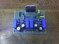
Woohoo! International mail FINALLY got me my boards from Olimex (the self etched prototype sort of sucked), but still no transistors. Everything else is primed and ready to go when they come in. I have already made several adjustments to the board and am planning on making it a two layer board if I ever order more or want to change components drastically.
PS Sorry for the bad picture. All I have is the camera on my phone, and as I am sure you see, it rather sucks, but you should get the point.
PS Sorry for the bad picture. All I have is the camera on my phone, and as I am sure you see, it rather sucks, but you should get the point.
Attachments
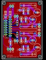
So, after putting these boards together, I made a bunch of changes. Most notably, I made the drill holes for the chip too small! 😱
Here is the latest revision. It is basically the same layout, but I changed the drill hole sizes, made it two sided to ease some routing issues, beefed up the signal lines (again due to the two sided board), moved the decoupling caps closer to the chip pins, made the pinheaders segmented where it made sense instead of having all individual pins, and improved the ground plane.
If there are suggestions, please let me know! I have had a couple of request for boards, but I have not had time to fully test the board, so I am a little hesitant to recommend them to any one else yet. Keep an eye on the thread, though! I am sure that when the kinks get ironed out I will post the Eagle files or order a few boards for everybody or something. . . 😀
Attachments
Looks great! I have a power supply ready to go, two chips...
But I have not seen a consensus on output stage... Any MORE ideas?
Thanks to all!
Peace,
Keith
But I have not seen a consensus on output stage... Any MORE ideas?
Thanks to all!
Peace,
Keith
I have some SAP16N and SAP16P's I got from the UK a couple weeks ago -- these make the design a breeze -- no need for a VBE multiplier -- although I haven't yet had boards burned. It was very, very easy ordering from Profusion's website in the UK.
jack
jack
I don't think there is one yet, but I am sure people will be posting what they are doing and how it turned out. Stay tuned!!!djkib said:I have not seen a consensus on output stage... Any MORE ideas?
David
Good work,dfdye,
I'd better like the IC and transistor designed on one PCB,could u make one again?thanks!
Gooday
I'd better like the IC and transistor designed on one PCB,could u make one again?thanks!
Gooday
Glad you like the board!gooday said:Good work,dfdye,
I'd better like the IC and transistor designed on one PCB,could u make one again?thanks!
Gooday
I was staying away from the transistors being on the same board since I would like to try some different output stages and designs. Also, I have a bunch of TO-3 transisitors that I am going to wire p2p for the initial output stage (once the last of them come in--they are currently on backorder). I wanted to maintain flexability since I am not sure what I want in the output stage yet.
That being said, if I end up using TO-247 transistors I may make an output board or integrate the output stage into a different design, but I haven't really planned on doing that as of right now. If I do, I will rethink a few aspects of the board to try and protect the signal paths a little better. This weekend I hope to finish up the power supply and check out the stage that is finished with a function generator. I'll be sure to let everyone know how it turns out, but I wish I had all of my transistors to let you know how it sounds! 😀
gooday said:Good work,dfdye,
I'd better like the IC and transistor designed on one PCB,could u make one again?thanks!
Gooday
the easiest way of doing this is with 2 pcb's -- this is how Audio Research did some of their amplifiers -- the output stage board with the transistors mounts directly on the heat sink. The TO3 devices are mounted on the heatsink and soldered into place. Since we are experimenting here you could use Keystone transistor sockets instead. The nice thing about the Audio Research board is that it can be entirely removed, unsoldered from the VAS stage, if there is a problem with the output devices.
The TO247 devices make this a lot easier as they will mount vertically, right onto the heatsink.
- Status
- Not open for further replies.
- Home
- Amplifiers
- Chip Amps
- Lm4702