Alright, time to get the ball rolling on making some PCB's. Since I am still REALLY new at this, I figured I would run a design by you guys to see if I am anywhere near the right way of thinking about this.
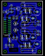
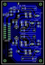
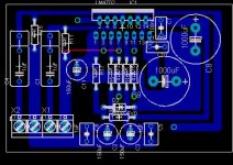
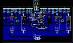
The resistors are all vertically mounted to allow a variety of different sizes/brands to be used. The thinking was that using 1/2W resistors would be easier with this configuration without taking up a ton of real estate on the board. I know the silk screen layer overlaps in several places, but I am planning on etching these at home and not applying a silk screen. (however, is there a way to move labels in Eagle without moving the whole component?)
After the discussion over using bipolar electrolytic input caps and bypassing them with film caps, I put in space for using 1uf film caps paralleled with 33uf electrolytics. I noticed on Russ’s boards (which, with apologies to Russ for my bad design , was the starting point for this board) that there are larger electrolytics on the power inputs that I am not 100% sure the purpose of (are these additional reserve caps, or are you putting in power directly from the transformers here and using these as smoothing caps?) The parts I have tentatively picked out for the comp caps (CC1&2) are ceramic, though if there is some reason I shouldn’t use ceramic in a circuit, I would love to hear some alternate suggestions!
Thanks!!!
The resistors are all vertically mounted to allow a variety of different sizes/brands to be used. The thinking was that using 1/2W resistors would be easier with this configuration without taking up a ton of real estate on the board. I know the silk screen layer overlaps in several places, but I am planning on etching these at home and not applying a silk screen. (however, is there a way to move labels in Eagle without moving the whole component?)
After the discussion over using bipolar electrolytic input caps and bypassing them with film caps, I put in space for using 1uf film caps paralleled with 33uf electrolytics. I noticed on Russ’s boards (which, with apologies to Russ for my bad design
, was the starting point for this board) that there are larger electrolytics on the power inputs that I am not 100% sure the purpose of (are these additional reserve caps, or are you putting in power directly from the transformers here and using these as smoothing caps?) The parts I have tentatively picked out for the comp caps (CC1&2) are ceramic, though if there is some reason I shouldn’t use ceramic in a circuit, I would love to hear some alternate suggestions!Thanks!!!
Attachments
I will definitely let you know when the prototype is up and working (hopefully some time within the next week if all of the parts get here, but that may be a little optomistic!), but I am having a hell of a time getting some of the more fine traces to transfer to the blank PCB's. So far I have used Epson Photo paper, Laser overhead and inkjet overhead material as toner transfer material, and I think that I just need a little more practice to get the fine traces around the chip to come out clean. For now, it is all sharpie!
I'll be etching the first board this afternoon.
I'll be etching the first board this afternoon.
Interesting suggestion. I am not sure if anybody has a working amp up and running yet (though I bet Russ has by now), but as soon as I get my transistors in, I will start playing around.
In the mean time, I have ruined several blank PCB's trying to get good home brewed boards.
Olimex here I come!!! Oh, and I fixed/tweaked a few more items on the boards. Once I'm happy with the final versions, I'll post in case somebody wants one.
David
In the mean time, I have ruined several blank PCB's trying to get good home brewed boards.
Olimex here I come!!! Oh, and I fixed/tweaked a few more items on the boards. Once I'm happy with the final versions, I'll post in case somebody wants one.
David
Russ White said:I just haven't been able to find any film cap in 10uf that size anywhere, not just in US.
wrt 10uF input caps -- MKS suggested a few week back --
the usual suspects for WIMA's are Mouser and Future -- neither have this bird (MKS 10uF) in stock -- ASC's are pretty big -- but very good quality -- this cap doesn't have to be placed on the input board -- Audio Research places it on a pair of standoffs adjacent to the RCA input jack on their D120 amplifier.
You can occasionally find high cap ASC's and General Electric polycarbonates on EBay. Expect to pay over $10 a piece if you have to go through Allied or Newark.
Hi Jackinnj,
LM4702, BD139, MJE15034/MJE15035, TIP3055/2955 (currently used for testing) is mounted on the same heatsink.
The power supply is +/-34V. The heatsink is cool when bias is set to 30mA and it just keep on increasing until I switch it off at around 300mA. FYI, i've build a Douglas Self Blamesless amp before without having this problem. Pls help.
Regards.
ok
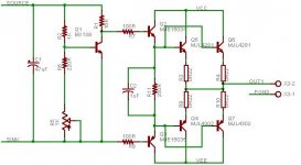
first, the LM4702 is the input and VAS stage and it probably shouldn't go on the same heat sink as the Output Stage -- i don't think that this is a major difference. the LM4702 is going to dissipate about 25ma times the absolute value of the rail voltage so it doesn't require a large heat sink --
the LM4702 is capable of sourcing/sinking some tens of milliamps -- so I trust that your output transistors are set up in Darlington configuration -- the beta of the 2955 and 3055's is comparatively low -- the MJ11032/33 has a beta of around 1,000.
i wonder a bit whether the resistor values specified by the Nat Semi pdf for the VBE multiplier are correct -- I would think you should have a trimmer so that you could adjust the current...i will try this out in the lab tomorrow.
the knowledge base on these driver ships is just being developed -- I note that Digikey shipped me some 4702A's which are supposedly still in the developmental stage --
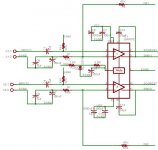
Now that I am getting close to putting together the output stage of the amp, I was wondering how Russ and others are using the thermally compensated transistors. I know that the SAP16's were suggested, but I wasn't really sure how these would be wired up. If Russ or somebody else could post a simple schematic of how these would be used, I would grately appreciate it! (Still learning!)
I am still planning on using regular transistors for the first itteration, but I would love to have some more options for future tries.
Thanks in advance!
I am still planning on using regular transistors for the first itteration, but I would love to have some more options for future tries.
Thanks in advance!
dfdye said:If Russ or somebody else could post a simple schematic of how these would be used, I would grately appreciate it! (Still learning!)
I am still planning on using regular transistors for the first itteration, but I would love to have some more options for future tries.
Thanks in advance!
Hi dfdye,
I have had my 4702s for quite some time, and have been working on a couple of possible layouts, but I have been quite busy over in the Pass Labs forum with a Zen V9 and my Twisted XBOSOZ, so I really have put this project on the shelf for now, I expect to get back to it shortly though. I think using the SAP16 will be one of the simplest most straight forward ways to get one of these going. It is a darlington so driver current demands are low, and it is thermally protected and has a minimum of external components. I will post more on the subject as time permits.
Cheers!
Russ
- Status
- This old topic is closed. If you want to reopen this topic, contact a moderator using the "Report Post" button.
- Home
- Amplifiers
- Chip Amps
- Lm4702