I’m building a class D amplifier using the LM4651 and LM4652 chip set I intend to provide two full range and a subwoofer/ low pass channel. Power will be provided by three separate toroidal transformers to avoid crosstalk and something like 30 and 18 odd thousand uF on the board which I hope will stabilise it without regulators. Any comments on this are welcome.
I’ve simulated a filter system which seems to work quite well which hopefully I can post here somewhere, but how does this affect the input resistance the main amplifier is required to see or match with the “values” of R1, R2 (not their ratio) and RLP, CLP should they be removed with such an active filter?
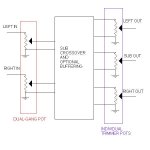
Is this a good way to take a low pass from a stereo signal?
Any has anybody please got any ideas on how to implement a volume control on such a beast?
Cheers from spud
🙁
I’ve simulated a filter system which seems to work quite well which hopefully I can post here somewhere, but how does this affect the input resistance the main amplifier is required to see or match with the “values” of R1, R2 (not their ratio) and RLP, CLP should they be removed with such an active filter?
Is this a good way to take a low pass from a stereo signal?
Any has anybody please got any ideas on how to implement a volume control on such a beast?
Cheers from spud
🙁
Attachments
I suggest that you move your thread to Amplifiers - Class D forum, im sure you will find more help there than here.
Which i could help but i dont know anything about class D. try asking less questions at once, and more specific ones. (lazy  ) people will tend to help more in those cases.
) people will tend to help more in those cases. cool smilies eh?
Re: reply to homer
Your title actually has very little to do with your post. Your question is really about a subwoofer crossover and the fact you are using LM465x is irrelevant to this question.
Basically, you will need 1 volume control between the source and your filter stage. Then you will need 3 controls (you can use trimmers if you want) to vary the sound level coming out of each power amp. You adjust the 3 controls to match it so it sounds right and leave those alone, and just use the 1 single control everyday.
spudspud said:tried that and had absolutly no replies in ages, don't know what i'm doing wrong
Your title actually has very little to do with your post. Your question is really about a subwoofer crossover and the fact you are using LM465x is irrelevant to this question.
Basically, you will need 1 volume control between the source and your filter stage. Then you will need 3 controls (you can use trimmers if you want) to vary the sound level coming out of each power amp. You adjust the 3 controls to match it so it sounds right and leave those alone, and just use the 1 single control everyday.
will there not be a lot of noise on the output if i remove the signal but the gain remains the same. I thought i had to attenuate the whole lot on the OP but this would create a lot of heat and theirs where i get confused. 
spudspud said:will there not be a lot of noise on the output if i remove the signal but the gain remains the same. I thought i had to attenuate the whole lot on the OP but this would create a lot of heat and theirs where i get confused.
I don't understand. Please be more detailed. Remove signal from what, the filter stage input? Create a lot of heat where? An op amp driving against a pot will not create much heat, your standard 1/8W or what cheapo potentiometer will do.
Re: reply to homer
I think it would help if you posted a legible schematic, preferrably one that's not inside a zip file. I have no idea which resistor is R1 or R2, or what RLP and CLP is.
As far as I can make out you have two low pass filters per channel, and you've connected the outputs of two of those together, presumably for the sub-woofer. That won't work. Remove one of the op amps for the sub output and bring the input 1k resistors coming from the filters together to the inverting input of the remaining op amp.
You can actually save some components by adding the channels first, and filtering the sub-woofer after the adder. Same end result.
In general, a reasonably well designed filter will produce neglible noise at power amp signal levels, so I don't know what you're worried there.
Rune
spudspud said:tried that and had absolutly no replies in ages, don't know what i'm doing wrong
I think it would help if you posted a legible schematic
, preferrably one that's not inside a zip file. I have no idea which resistor is R1 or R2, or what RLP and CLP is.As far as I can make out you have two low pass filters per channel, and you've connected the outputs of two of those together, presumably for the sub-woofer. That won't work. Remove one of the op amps for the sub output and bring the input 1k resistors coming from the filters together to the inverting input of the remaining op amp.
You can actually save some components by adding the channels first, and filtering the sub-woofer after the adder. Same end result.
In general, a reasonably well designed filter will produce neglible noise at power amp signal levels, so I don't know what you're worried there.
Rune
Any reason you dont want to use the examples in the datasheet?
Im probably just going to make the PCB given in the datasheet as thats the easiest...
Only problem is there are no drill holes in their pcbs.. (anyone know if they have eagle files for these examples?)
Oh and the Reference PCB would be the one for a subwoofer right?
thx
Im probably just going to make the PCB given in the datasheet as thats the easiest...
Only problem is there are no drill holes in their pcbs.. (anyone know if they have eagle files for these examples?)
Oh and the Reference PCB would be the one for a subwoofer right?
thx
ok ignore what I said theres only a simple filter in the datasheet...
btw your image is hard to see the values, assuming you used a program to calculate the crossovers you should be fine.
btw I've seen people add some 100 ohm resistors and small caps on the outputs of each op-amp for these kind of filters. Dont know if its necessary.
btw your image is hard to see the values, assuming you used a program to calculate the crossovers you should be fine.
btw I've seen people add some 100 ohm resistors and small caps on the outputs of each op-amp for these kind of filters. Dont know if its necessary.
reply to thomas
good to find somebody on the same project as me!
At times i've been a bit
anyway in answer to your drill hole question there's some gerber files on the national sems site which I d'loaded a free prog called viewmate which can open them, only prob is you can only print one layer at a time, so you have to line em up.
are you using a switchmode or linear PSU?
to the matey who said I shoud tie the line together B4 the lowpass filter, wouldn't that ruin the stereo effect of the full range line. Please could you elaborate on why it wouldn't work as I simulated it and it seemed to.😕
To leadbelly
yeah I thought if I remove the signal at the input to the filter or main amp i would still have +125W of noise/hiss on the output unless I attenuate it there (at the OP to the speaker) which is where i got the idea it would get hot.
I'm here cos my teachers are industrial/ military trained an know 🤐 all about amps, and this is my first time so please try to be patient with my questions
R1 and R2 are input resistor which set the gain by their ratio, but i think their value is meant to be relvent to the OP of the filter.
yeah I thought if I remove the signal at the input to the filter or main amp i would still have +125W of noise/hiss on the output unless I attenuate it there (at the OP to the speaker) which is where i got the idea it would get hot.
I'm here cos my teachers are industrial/ military trained an know 🤐 all about amps, and this is my first time so please try to be patient with my
questionsR1 and R2 are input resistor which set the gain by their ratio, but i think their value is meant to be relvent to the OP of the filter.
Re: To leadbelly
This is sort of what I was getting at. How you are building the power amps has nothing to do with it, all your volume adjustments are BEFORE the input to each of your 3 power amp channels.
spudspud said:yeah I thought if I remove the signal at the input to the filter or main amp i would still have +125W of noise/hiss on the output unless I attenuate it there (at the OP to the speaker) which is where i got the idea it would get hot.
This is sort of what I was getting at. How you are building the power amps has nothing to do with it, all your volume adjustments are BEFORE the input to each of your 3 power amp channels.
Attachments
Hi there
The LM4651 datasheet has an example of an active filter input stage. Are you getting PCBs made for this? I would be interested if they aren't real expensive.
The LM4651 datasheet has an example of an active filter input stage. Are you getting PCBs made for this? I would be interested if they aren't real expensive.
Re: reply to thomas
Cant seem to find the Gerber files on their site.. but is it just drill specs no eagle pcb files or anything?
because I just want to print the boards myself and leave white spots where the holes should be drilled.
No idea what psu Im going to be using yet...
spudspud said:good to find somebody on the same project as me!
At times i've been a bit
anyway in answer to your drill hole question there's some gerber files on the national sems site which I d'loaded a free prog called viewmate which can open them, only prob is you can only print one layer at a time, so you have to line em up.
are you using a switchmode or linear PSU?
Cant seem to find the Gerber files on their site.. but is it just drill specs no eagle pcb files or anything?
because I just want to print the boards myself and leave white spots where the holes should be drilled.
No idea what psu Im going to be using yet...
to thomas I'll put gerbers and other stuff in a zip attatched to this, but you will need to download a prog to view em with, I found one called Viewmate and its free I'll try to put it in the zip folder . There are others but some don't work cos I d'loaded a different one at college and that didn't, anyway goodluck, especially wi yer PSU requirements, get back if yer stuck and i'll tell yer how mine comes on, waiting for parts at mo cos tis bank hols over ere.
Thanks leadbelly, I'll try your method of vol control.
Did somebody say my filter design wouldn't work, cos if yer know more than me (which ain't a lot ) please do tell B4 I go further.
To whoever asked to buy em, I'll be designing the layout then the lab assistant at college will be producing em but I hope to get my own stuff to DIY eventually. Will post up my PCB design when done if any use to yer, get back to me.
I'll try to put it in the zip folder . There are others but some don't work cos I d'loaded a different one at college and that didn't, anyway goodluck, especially wi yer PSU requirements, get back if yer stuck and i'll tell yer how mine comes on, waiting for parts at mo cos tis bank hols over ere.Thanks leadbelly, I'll try your method of vol control.
Did somebody say my filter design wouldn't work, cos if yer know more than me (which ain't a lot ) please do tell B4 I go further.
To whoever asked to buy em, I'll be designing the layout then the lab assistant at college will be producing em but I hope to get my own stuff to DIY eventually. Will post up my PCB design when done if any use to yer, get back to me.
too big aparently, so heres the address
http://www.national.com/appinfo/audio/0,1819,968,00.html
theres a list there of various devices🙂
signing off now so catch yer next time😱
http://www.national.com/appinfo/audio/0,1819,968,00.html
theres a list there of various devices🙂
signing off now so catch yer next time😱
spudspud said:too big aparently, so heres the address
http://www.national.com/appinfo/audio/0,1819,968,00.html
theres a list there of various devices🙂
signing off now so catch yer next time😱
thanks
Might take a bit of work to figure out how to photoshop that somehow into the pdf to make drill holes..
hm
btw I also found this nice design spreadsheet on the audio section of the site, if you havent checked it out already:
http://www.national.com/appinfo/audio/files/ClassD_Design_Guide13.xls
- Status
- Not open for further replies.
- Home
- Amplifiers
- Chip Amps
- Lm4651, Lm4652