xplod1236 !
I have made one PCb fo r the LM4651/52 chip-set, it was like a "first shoot" and I am working on a version 2.0, so if you can waite......................................
Have fun
Thomas
I have made one PCb fo r the LM4651/52 chip-set, it was like a "first shoot" and I am working on a version 2.0, so if you can waite......................................
Have fun
Thomas
I am interested to.......I have made one PCb fo r the LM4651/52 chip-set, it was like a "first shoot" and I am working on a version 2.0, so if you can waite......................................
Can't you take a photo and show us what you have so far?tlmadsen said:xplod1236 !
I have made one PCb fo r the LM4651/52 chip-set, it was like a "first shoot" and I am working on a version 2.0, so if you can waite......................................
If anyone needs any chipsets for these, I have had three sets sitting around for ages from a project that never got off the ground. Not too bothered about getting any cash for these, so I would swap for just about anything interesting.
Can't you take a photo and show us what you have so far?

Per-Anders, you are asking me to show my incompetence in public !!!
I think that I am in good hands here, so it is all right and I don't mind showing it¡_¡_¡_¡_¡_¡_¡_.
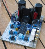
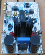
The PCB was made about 2 years ago and was declared "dead" about a year ago after extensive modification and experimentation of it. I had to remount the LM4651/52 chip-set, and the inductors again to take the picture (this is the reason that the LM4652 are not screwed on to the heatsink like it normally would).
All the op-amp socket is for all the "extra" circuit that I originally indented to be part of the design. It where to be a amplifier for a subwoofer and the next version would also be for subwoofer use, but there should not be anything preventing you form using it full range if you want that
The schematic was more or less on of the set-ups shows in the datasheet for the LM4651/52. It was not a problem to get the LM4651 to modulate, but it was a real "pain in the butt" to make it "interface" with the LM4652 and make that do the modulation as I recall it¡_¡_¡_¡_took forever and a lot of troubleshooting. When I finally got it to work I decided to go for a new interaction of the PCB (¡_¡_and I am coming around to do this now).
I have the following in mind for the new PCB (version 2.0):
A. On-board PSU (-trafo) like the first PCB. This can be seen on the pictures. All you would need to add would be a transformer.
B. Same inductors as the first PCB. Can also be seen on the pictures. They are from CoilCraft.
C. Other type of connectors for the trafo. Some kind where you "squeeze" the wire, since the wires coming form a trafo are offend single stranded, which makes them difficult to use with the Faston-type of connecter I originally used.
D. The LM4652 will be moved out to the side of the PCB so an external heatsink can be used. If you mount the PCB into some kind of chassis you can use that as heatsink. It really doesn't get very hot.
E. To types of input, both "mono". One called "direct" without any kind of filter and the other one with a fixed 4.order lowpass. The first one is to be used if your SS-amplifier already has a good lowpass filter build in. (not many have!!).
F. After the input section the signal goes to a "linkwitz"- seal boxed EQ (I love that stuff).
G. Maybe an "Auto on/off"-circuit. This would just bring the chip-set into stand-by.
H. No fuses as there are on the first version. If everything works you don't really need them. If you "kill" one of the chips the modulation are likely to stop the same second, so¡_¡_¡_¡_
I. The size of the PCB shown on the pictures is standard EURO-board size, i.e. 100 x 160 mm (¡Ö 4" x 6.3/8"). The new board are expected to be slightly smaller than this.
J. I expect that a board like this could be sold for around US$ 15-20.- + P & P. (¡Ö US$ 6.-). Maybe a complete kit (-trafo) could be made for around US$ 70-100, but I can't buy components very cheap (here in Denmark), so it is most likely cheaper for you to get the components your self.
K. I expect to have a board ready in anything from 2 month to 12 month from now, so you might want to go somewhere else and find one......................
Comment and suggestions are very welcome indeed.
Regards
Thomas
(Maker of "Das Modul")
Attachments
A prototype can look like anything.... compare Gaincard!tlmadsen said:
Per-Anders, you are asking me to show my incompetence in public !!!
Nice job so far

About the screwholes. My look like this
http://home5.swipnet.se/~w-50674/hifi_pics/hifi_100pr/qsxpsr1.jpg
I try to have "clean" holes, non-plated.
Your input connectors: Why haven't you placed them at the card edge? Easier if you want them in a the back panel.
Rectifier bridge, cooling?
OK, I didn't read to carefully but point C, how about Wago, like I use? See the picture I have linked.
L's, how about the shape of these inductors, radiation?
I think it's an advantage if you have the heatsink on the pcb. I think you can achieve a better pcb layout in respect to EMI problems. 170 Watt out 17 watts heat at the most, not very much.
I think this particular design should be done in SMD just because of all switching. Compactness is a virtue here.
Will you try the 2nd version soon and make it available?I have the following in mind for the new PCB (version 2.0):
I certainly would be interested 😀
We need some competition with the expensive ZAP modules from LCAUDIO. (Well, expensive for my taste)
When building a multiple channel amp, wouldn't it be better to have the lm4652 chips on the edges of the pcbs? That way, they can all be mounted onto one bigger heatsink.
hey thomas,
would you be able to post the PCB layouts from version one here?
i really want to build a 4651/2 amp but don't have the money to buy a PCB, so i need to make it by hand.
would you be able to post the PCB layouts from version one here?
i really want to build a 4651/2 amp but don't have the money to buy a PCB, so i need to make it by hand.
"When building a multiple channel amp, wouldn't it be better to have the lm4652 chips on the edges of the pcbs? That way, they can all be mounted onto one bigger heatsink."
-eh, it's a class D amp, so it should be fairly efficient.
i may think of making a board for this someday, but probably not. i figure i'll just use the lm4780s anyways -- fewer components and all.
-eh, it's a class D amp, so it should be fairly efficient.
i may think of making a board for this someday, but probably not. i figure i'll just use the lm4780s anyways -- fewer components and all.
Soundnerd
I think it would be bad "time-management" from my side to post the layout of my PCB. It would mean that I would have to spend time explaning what changes to be made ans so on............
I prefer to spend my limited time a new layout (version 2.0).
I hope you understand my position.
If I can make and sell a version 2.0 for less than US$ 20, do you still think that you can og will make it (cheaper) yourself ?? (if the moderate think this is too "commercial" just drop the line. However, I have a hard time seeing how we should have a forum without PCB's...................and they do cost money)
I will keep you all informed about my progress.
Thomas
Good luck with your efforts.
The golden rule: Keep it compact in order to reduce EMI. SMD is also to consider just because of the nature of the design.
The golden rule: Keep it compact in order to reduce EMI. SMD is also to consider just because of the nature of the design.
Thomas,
I was just searching through the forums, and found this post. It's been a while and I was wondering if you have made any progress with the design?
-Mike
I was just searching through the forums, and found this post. It's been a while and I was wondering if you have made any progress with the design?
-Mike
Couple comments. From the small size of your layout the worst EMI area will be the output indcutors. The two easiest ways to control EMI will be to put the whole thing in a box (faraday cage) or switch those inductors to torroids. The torroids will reduce your EMI significantly but will also get hotter even when running no load. As for THD+N performance, the ones you are using are pretty good. You might also want to look at the full range layout (callede 4.1) on National's site because this layout has the LM4652 on the edge like you want to do. Just be sure to keep the gate traces from the LM4651 to the LM4652 as short as possible and have the option for gate resistors, which your pics seem to show.
-SL
-SL
Dear soundNerd
I am sorry to say that a new and better version is still only in "electronic format" and I don´t forsee that to change in the near future. Sorry................
Regards
Thomas
I am sorry to say that a new and better version is still only in "electronic format" and I don´t forsee that to change in the near future. Sorry................
Regards
Thomas
- Status
- Not open for further replies.
- Home
- Amplifiers
- Chip Amps
- LM4651/4652 pcb?