I was advised that LM4562 were the best choice for the preamp in my headunit. I have fitted them today and although they sound excellent i am pretty sure they are oscillating as they are running very hot. (just shy of 60 degrees celcius) This is the circuit diagram for where they are at present. I don't know whether the opamp on the tone control is also getting hot as it's inaccessible whilst the unit is on.
A common mod i've seen done is to replace the 10uF capacitors (C450/457/470/477) with 47uF. Would i be better off trying to find a more suitable opamp or should i try to get this one to work properly?
An externally hosted image should be here but it was not working when we last tested it.
A common mod i've seen done is to replace the 10uF capacitors (C450/457/470/477) with 47uF. Would i be better off trying to find a more suitable opamp or should i try to get this one to work properly?
I doubt changing those caps will help. The circuit is already bypassed, though I don't know where the caps are located The 4562 is fast and the bypass caps need to be very close. Though one of the best out there, if the circuit isn't laid out well or has some quirk that leads to oscillation, it's not a good choice of part. If you have a scope and some time to experiment, you might sort it out with bypasses located closer, or some series resistance in a particular location. If not, a different part might be better.
It's a unity gain stable device. If the layout is decent and suitably decoupled, your problem is in overall loop compensation - and that's not the opamps fault.
Can you post a scope shot of the output - we may be able offer more advice looking at it.
BTW I assume the devices are in the right way around ;-)
Can you post a scope shot of the output - we may be able offer more advice looking at it.
BTW I assume the devices are in the right way around ;-)
This excerpt is from the LM4672 data sheet pg 24 top
The LM4562 is a high speed op amp with excellent phase margin and stability. Capacitive loads up to 100pF will cause little change in the phase characteristics of the amplifiers and are therefore allowable. Capacitive loads greater than 100pF must be isolated from the output. The most straightforward way to do this is to put a resistor in series with the output. This resistor will also prevent excess power dissipation if the output is accidentally shorted.
I dislike schematics with 'pictorial' ICs rather than the conventional triangle symbol as it's difficult to envision where the output is. Your circuit has LOTS of outputs directly driving the next stage. Some strategically placed low value resistors (27-100 ohms) on each output directly at the pin may very likely settle it down. Improved bypassing would be a plus.
G²
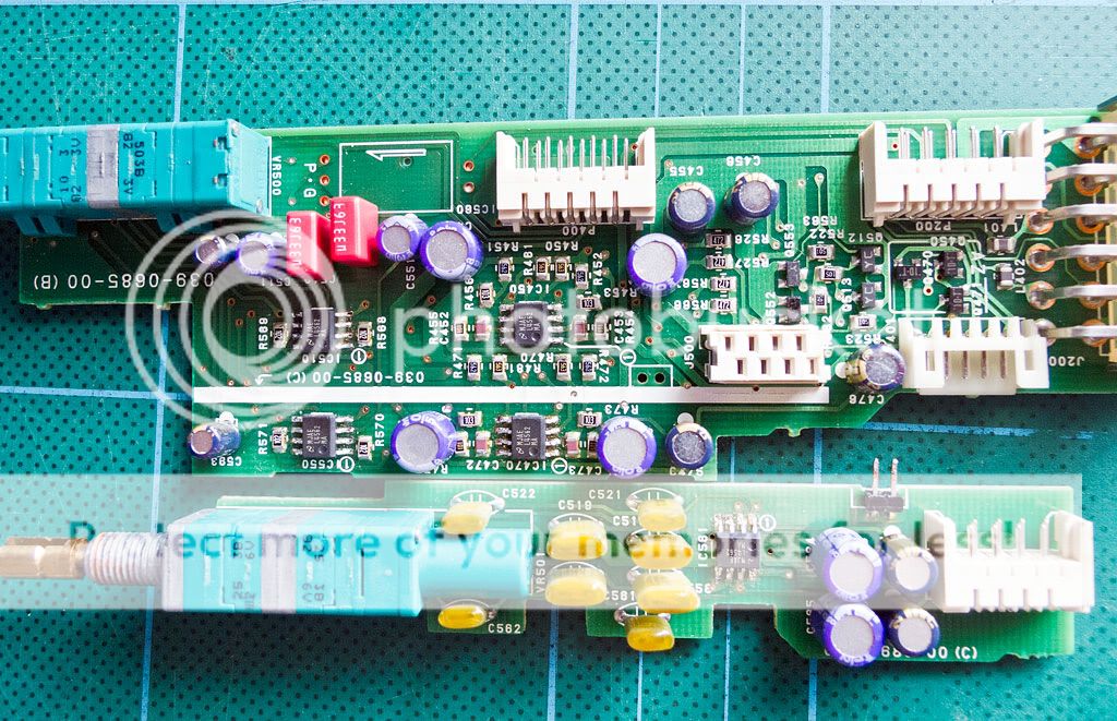
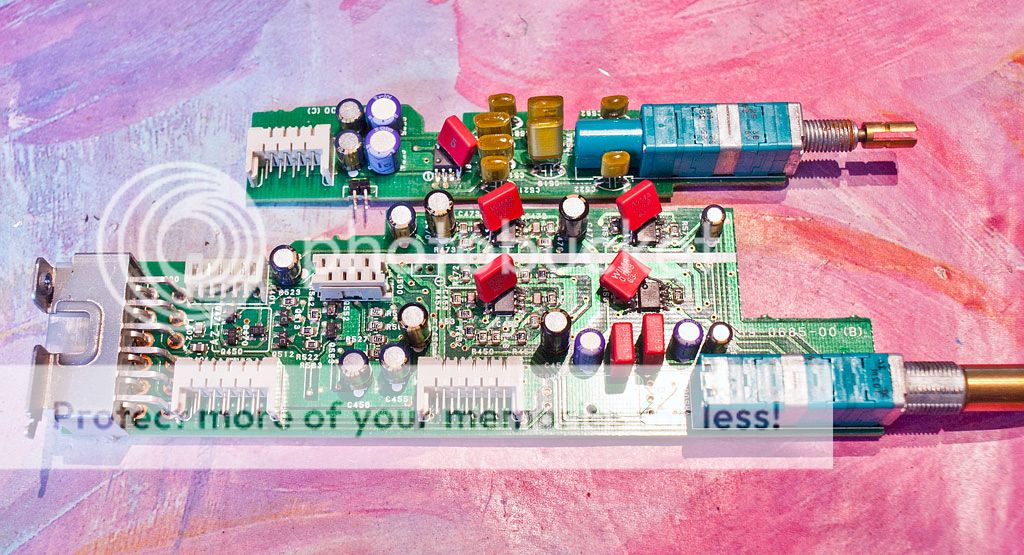
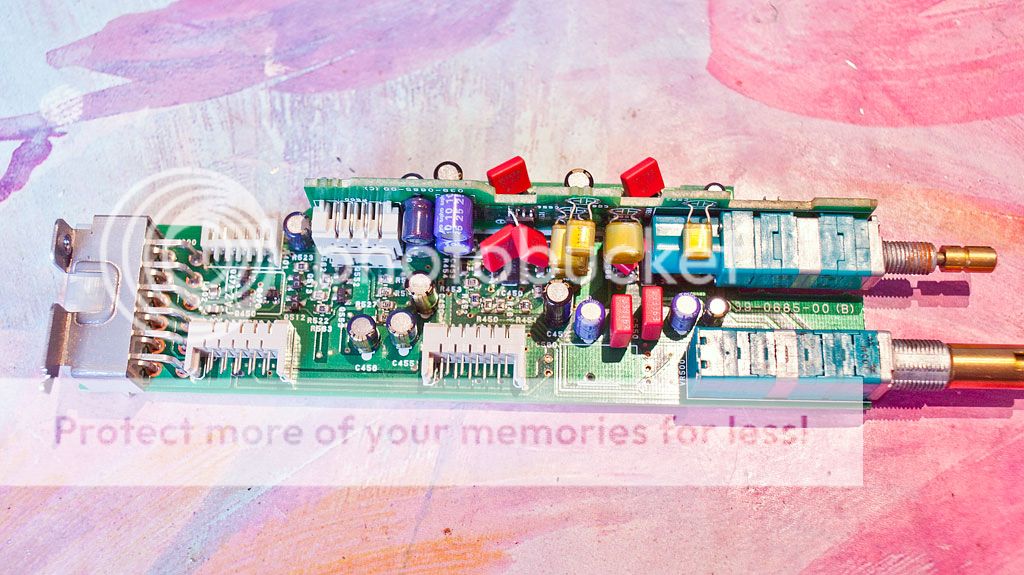
Devices are the correct way around. Sadly i don't own a scope and can't actually prove they are oscillating but they are running far too hot compared to the original devices which ran almost at ambient. (the originals were 3x uPC4570 and 2x NJM4580. I ran this with the NJM4580's swapped out for OP275 from a japanese version) Adding components to the circuit isn't really possible as the circuit is too small and cramped to make it possible. This is the pcb design we are dealing with. Its a high voltage preamp for a car radio. (4V out and 9V maximum unclipped with EQ)
Hi, please try the smallest 10 nF cap you can find with the right voltage specs directly from the + to - pin of the opamps. So directly under the PCB or above the opamps. Prefab the caps lead wires with pliers so that lead wires are very short.
There might be nothing wrong. The LM4562 quiescent current is quite high at typically 10 mA. With a + 15 V / - 15 V supply the power dissipation is 300 mW so I would expect an SO8 package to run warm to the touch. If you were here in England in the spring that we are having any heating is a bonus.
I haven't compared the quiescent currents of the parts replaced but they are likely to be lower.
I haven't compared the quiescent currents of the parts replaced but they are likely to be lower.
The operating current of NJM4580 is typically 6mA (max of 9mA), uPC4570 is 5mA (max of 8mA) and OP275 says max supply current of 5mA.
Jean-paul is that 10nF across pins 4 and 8? I don't have any 10nF capacitors in my collection. Closest value i have in any quantity are 6.8nF, but they are quite large styrol caps. (7mm leg spacing and the legs are 5mm long) Only other values that i have lying around are 1nF, 47nF, 56nF and 100nF.
Jean-paul is that 10nF across pins 4 and 8? I don't have any 10nF capacitors in my collection. Closest value i have in any quantity are 6.8nF, but they are quite large styrol caps. (7mm leg spacing and the legs are 5mm long) Only other values that i have lying around are 1nF, 47nF, 56nF and 100nF.
film caps won't help anything. Too much inductance. Electrolytic caps won't help anything, too much inductance. You need to put 0.1 uf ceramic caps between 8 and 4 of the back of the socket (power pins) and you need to put about a 22 pf ceramic caps between 7 and 6 and also between 2 and 1, Unless they are a direct short. I did this on my ST33078s, killed the oscillation. The way I knew I had oscillation before I put the scope on , the power amp fan was running full blast. The op amps were in the disco mixer, had been slow old 4558s.
I actually put the 0.1 uf's about an inch away from each pair of op amps by drilling new holes in the PCB, but the nearness to the op amp is important. LM4562's are faster slew rate even than ST33078's.
I actually put the 0.1 uf's about an inch away from each pair of op amps by drilling new holes in the PCB, but the nearness to the op amp is important. LM4562's are faster slew rate even than ST33078's.
Last edited:
Not sure I can reliably read the part number locations accurately, but there’s some 56K resistors going to ground from pins 3 and 5 of the OP275 locations. Might want to try putting some 100 pF caps across those to see if it helps.
You can use values from 10 to 220 nF without any problem but I advised 10 nF because of their size. I have 10 nF MKT in a very small size (read: thin) for that purpose. Never had a problem with their inductance but I did have problems with ceramic caps (sound wise). Thins caps can be mounted "laying" on the opamps which will require some skills with bending the wires.
Modern C0G of X7R ceramic caps are OK but AFAIK they are mostly SMD.
Modern C0G of X7R ceramic caps are OK but AFAIK they are mostly SMD.
I've put the spare standard board back in and it runs much cooler. The OP275 run at 38 degrees and the NJM4580 at about 42 degrees. There are a pair of OPA2604 in the DAC I/V that seem to run quite hot as standard (55 degrees) I'm wondering if this is just me being paranoid as it runs warmer with the LM4562. (with there being 5 of them it pushes the temperatures up a lot)
Until I get a scope to check, I can't be certain if it is oscillating or not. I was hoping others with more experience would be able to advise me as to whether the high operating temperatures were normal or whether they were a likely indication of oscillation.
The output sounds fine with nothing audibly out of the ordinary. With the unit fully reassembled and running IC550 is running at about 65 degrees.
The output sounds fine with nothing audibly out of the ordinary. With the unit fully reassembled and running IC550 is running at about 65 degrees.
I am a little confused by the LM4652 data sheet but assuming that the Thermal resistance, junction to ambient, = 145 degrees / Watt. With the quiescent dissipation of 300 mW the temperature rise = 0.3 x 145 = 43.5 degees. Assuming an ambient of 25 degrees C the junction temperature = 25 + 43.5 = 68.5. I am guessing that because the Small Outline package doesn't have much plastic or metal surrounding it that the temperature on the top might not be that much lower so around 60 degrees depending on the board / case / temperature measurement technique/ quiescent current tolerance isn't too far away from prediction. Also the reality is that all numbers in thermal calculations are not well known (without vast amounts of effort even if the data was available) so the only way to get real answers is to build and try.
I think that an Oscilloscope is really required to know for sure if there are stability problems.
I think that an Oscilloscope is really required to know for sure if there are stability problems.
Just out of interest is there a better opamp out there that might be better suited to the job than the 4562's that I've fitted. Presumably something with a lower bandwidth that is closer to the originals might be a better bet.
Variations I've seen are:
LT1632
OP275 x 4 uPC4570 x1
uPC4570 x3 NJM4580 x2
Variations I've seen are:
LT1632
OP275 x 4 uPC4570 x1
uPC4570 x3 NJM4580 x2
Well I finally got around to pulling the unit back out of the car to sort this out. (the brightness and sharp sound was beginning to get to me) Took some fiddling to get the one cap in place under the tone pot, but it all came together. I used 68nF wima MKS which seems to have done the job as they sound much smoother now. Sounds like a completely different opamp, though it still runs reasonably warm its a fair bit cooler than before as i didn't manage to burn my fingers.
- Status
- Not open for further replies.
- Home
- Amplifiers
- Solid State
- LM4562 Oscillation