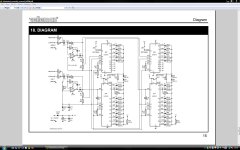
I think you asnwered your own question. JD1,2 connect pin 9 to Vcc or to the other connection to select DOT or BAR mode. Clearly, you want all four jumpers in the same position for a specific mode.
jd
jd
Hi
Thanks for the reply - I assumed i would jumper JB1,2,3 and 4 but wasnt sure about JD1 and 2.
Cheers
John
P.S We met at chesterfield UK at the diy meet.
Thanks for the reply - I assumed i would jumper JB1,2,3 and 4 but wasnt sure about JD1 and 2.
Cheers
John
P.S We met at chesterfield UK at the diy meet.
Last edited:
[snip]P.S We met at chesterfield UK at the diy meet.
To darned long ago - you guys should throw another one!
jd
I was thinking about having the bar/dot mode an option via a switch
Seems it may be a pain to figure out
John
Seems it may be a pain to figure out
John
I was thinking about having the bar/dot mode an option via a switch
Seems it may be a pain to figure out
John
Where's the pain? A DPDT switch?
jd
Yes was thinking about a pcb mounted DPDT switch for JB1,2,3 and 4 but what about JD1 and 2?
Cheers
John
Cheers
John
Last edited:
Yes was thinking about a pcb mounted DPDT switch for JB1,2,3 and 4 but what about JD1 and 2?
Cheers
John
OK for two channels you need a 4-pole switch, double throw. A bit less easy to find, yes.
Mouser gives 400 hits, like this one: PN42LESA02QE C&K Components Pushbutton Switches . $ 1.10 Or toggle types, hundreds.
http://nl.mouser.com/ProductDetail/...=sGAEpiMZZMvudeGI7i40XOzZDxmIb/GZekQAxW0k38g= $ 10
jd
Last edited:
What about JD1 and 2 are they shorted when JB1,2,3 and 4 are?
Cheers
John
The 3916 data sheet should tell you which is connected to which in which mode.
jd
The one thing that I did not like about the LM3196/5 is that the LEDs were not always hard on or off, but could appear to be fading on and off (i.e., those LEDs on the leading edge of the bar graph). I rather liked the fluorescent bar graph displays that were found in the Technics and Pioneer equipment of the time ('80s). Any options with regards to making the 3196 crcuit perform similarly?
🙂 Well page 9 and 10 of the data sheet (fig 1 and 2) show pin 9 connected for dot mode but on page 8 states leave the mode select pin open circuit!
Cheers
John
Cheers
John
Last edited:
Thanks to a user on head-fi who suggested JB1,2,3 and 4 the B meaning BAR
mode and JD1 and 2 the D meaning DOT mode!
Simple using a little logic...
John
mode and JD1 and 2 the D meaning DOT mode!
Simple using a little logic...
John
- Status
- Not open for further replies.
- Home
- Design & Build
- Construction Tips
- LM3916 VU meter circuit