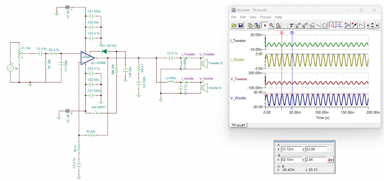
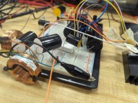
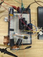
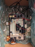
Here's a picture of the amplifier circuit I built and some transient analysis results from TINA TI. Everything looked good on the simulation (1V, 100Hz input signal, so the crossover even seems to be working). I'm trying to build it in person now and the rails are receiving the correct amount of voltage, the input is sending the correct signal, and everything is wired according to the diagram. Can someone tell me where I'm going wrong? I've attached some images of the circuit as well for reference.
Attachments

I would expect a lot of issues with oscillation with those long fly leads and plug board. I suggest building an actual PCB or wiring it up point-to-point directly on the IC.
You don't actually mention what the issue is. Do you not have any output on the LM3886? Is the output stuck at either rail? Is it oscillating? What??
I would scrap the zener diode in the mute circuit. Just make Cmute = 100 uF and Rmute = 33 kΩ as in the data sheet and you'll be fine. In fact, I bet the error in your circuit is found around the mute pin. Recall that you need to pull at least 500 uA out of the mute pin for the IC to UN-mute.
Tom
Sorry for being vague, the problem was the nothing was coming out of the output on pin 3 of the LM3886. I decided to scrap the mute function and leave pin 8 disconnected, if I can get it working I'll consider adding it back in (This way the amplifier should be "always on"). I'll try making C3 bigger and see if that helps. Where I'm at right now is the input is passing through the POT and input filters to Pin 10, and the bypass capacitors on the rails are working as well, sending +/-V to Pin 1 and 5 (+V) and to pin 4 (-V). I also connected pin 7 directly to ground. Any ideas on why it's not passing through?

That's your problem then. You need a minimum of 500 uA to flow in the MUTE pin for the LM3886 to enter active mode, i.e., to UN-mute. If you leave pin 8 disconnected 0 uA is flowing and the amp remains muted. Connect CM = 100 uF; RM = 33 kΩ and the chip will power up. You may get crappy performance due to the long wires but you should have an output.I decided to scrap the mute function and leave pin 8 disconnected
I write quite a bit about how the mute circuit works here: https://neurochrome.com/pages/grounding#Mute
He's not. I thought so at first too, but then noticed that the voltage is set to -36 V.Why are you feeding positive voltage on the negative rail?
Tom
Be sure to connect the cap C3 positive to the ground!I'll try making C3 bigger and see if that helps.
The other way around from normal.
That was the problem, I'm now getting output from the lm3886, thank you so much for your help!!!!That's your problem then. You need a minimum of 500 uA to flow in the MUTE pin for the LM3886 to enter active mode, i.e., to UN-mute. If you leave pin 8 disconnected 0 uA is flowing and the amp remains muted. Connect CM = 100 uF; RM = 33 kΩ and the chip will power up. You may get crappy performance due to the long wires but you should have an output.
I write quite a bit about how the mute circuit works here: https://neurochrome.com/pages/grounding#Mute
He's not. I thought so at first too, but then noticed that the voltage is set to -36 V.
Tom
That's "not wrong" as far as the circuit getting the correct voltage polarity, but it's frustrating to see a battery symbol, especially with a + on one side, set to output a negative voltage.He's not. I thought so at first too, but then noticed that the voltage is set to -36 V.
Tom
Maybe one should stick to propercircuit convention and less errors would be had. I have never seen a battery drawn like that having its cathode and anode swapped. Where did you people go to school?
We are here to correct , not berate.
Even I made same mistake of keeping mute pin open , as I was unsure about shorting it and destroying LM3886. Corrected it after re-reading the datasheet
Even I made same mistake of keeping mute pin open , as I was unsure about shorting it and destroying LM3886. Corrected it after re-reading the datasheet

Play nicely. Sometimes its just quicker and easier in a simulation to put a - in there rather than snip and rotate a symbol you realise has been placed incorrectly.
Well Mooly, if you make silly errors in schematics, it is not fair to seek advice to why it is not working. Any scholar would look for the onbvious first.
Nico, have to say it just looks like you are trying to justify that you missed the fact the symbol had a - designation by your continued posting... its not good optics to keep going on about it. What had happened with the voltage source was pointed out within minutes of you questioning it.
Looking at the waveforms in post #1 and you see they swing between -30 and +30 so the supplies must have been been correct. There is no functional error in the schematic as such even if it doesn't follow convention with that particular symbol and also the op did say at the outset that the sim worked correctly.
I miss things all the time on here and when I do I just say sorry, I hadn't spotted that. Works every time 🙂
- Home
- Amplifiers
- Chip Amps
- LM3886T Amp Circuit Not Working