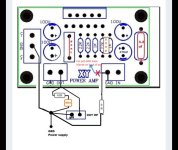
I bought two pairs of these boards to play around with and was hoping to get confirmation on some mods I saw on a thread in the attached picture.
Do these mods look correct to implement?
I just had questions:
- why the output is attached to ground via a 10R resistor and 68N capacitor
- is the larger .15 ohm 5W resistor bypassed here?
- is my star ground attached to chassis or floating?
- Finally, where is the best location to cut the trace on the board after the ground input? I understand I am just trying to remove the signal input ground from the PSU ground.
Thank you. Any other recommendations or modifications are appreciated.
Attachments
“-why the output is attached to ground via a 10R resistor and 68N capacitor”
RC series network is the Zobel network, usually 0.1-0.22uf + 2.7-10ohm/2-3w
“is the larger .15 ohm 5W resistor bypassed here?”
No need for that resistor, so it is bypassed.
Better if replaced with LR parallel combination called Thiele network
“Finally, where is the best location to cut the trace on the board after the ground input? “
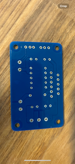
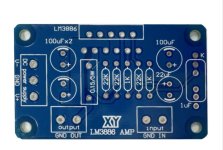
Can you post a couple of pictures of the boards , top and bottom?
RC series network is the Zobel network, usually 0.1-0.22uf + 2.7-10ohm/2-3w
“is the larger .15 ohm 5W resistor bypassed here?”
No need for that resistor, so it is bypassed.
Better if replaced with LR parallel combination called Thiele network
“Finally, where is the best location to cut the trace on the board after the ground input? “
Can you post a couple of pictures of the boards , top and bottom?