Hi,
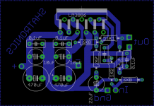
I have made my first pcb for lm3886 chipamp.
When I add supply it works because I can hear a little noise from the speaker and when I touch on the input it reacts, but after a few seconds it suddenly shut off.
Anyone have an idea of what the problem could be?
I have attached my pcb-layout.
Thank you,
Simon H.A.
Attachments
It's not hot at all. I have mounted it to an oversized heat sink and if I touch the chip it's cold.
Regards,
Simon H.A.
Regards,
Simon H.A.
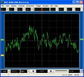
Is there a way I can test if it's HF oscillations? I don't hear any whizzing noice or so when it plays music.
Edit:
I checked with my oscilloscope to the output, and I see no oscillations at all.
Edit:
I checked with my oscilloscope to the output, and I see no oscillations at all.
Last edited:
hi, What are your power rails as you may not be drawing enough current from the mute pin to keep the amplifer out of mute.
Data sheet indicates you need RM = (|VEE| − 2.6V)/I8 where I8 >= 0.5 mA.
Regards,
Andrew
Data sheet indicates you need RM = (|VEE| − 2.6V)/I8 where I8 >= 0.5 mA.
Regards,
Andrew
Okay, I've discovered that if I connect the gnd from the supply to the speaker instead of the gnd from my amplifierboard It works until it starts clipping.
Edit:
I also discovered that the voltage from gnd -> "+" on my board measures 48V and from gnd -> "-" measures 0volt. How can that be true?
Edit:
I also discovered that the voltage from gnd -> "+" on my board measures 48V and from gnd -> "-" measures 0volt. How can that be true?
Last edited:
Okay, I've discovered that if I connect the gnd from the supply to the speaker instead of the gnd from my amplifierboard It works until it starts clipping.
Edit:
I also discovered that the voltage from gnd -> "+" on my board measures 48V and from gnd -> "-" measures 0volt. How can that be true?
Sounds like you have a short between Ground and the negative rail. though how it would work at all with that is beyond me... Also the fact that when you connect gnd to the speaker out instead of the gnd connection tends to imply that you have a break in the circuit between the main ground (between the caps) and the speaker out gnd... though looking at your board that seems unlikely...
I'd check for solder bridges between the negative rail and the Grnd lines (close to the chip they seem pretty close together.
Tony.
There are no short cuts between gnd and negative supply.
Maybe it's the chip that there someting wrong with?
I took it from an old amplifier my brother found at his apartment at the garbage.
It was from an old PA speakerbox.
Regards,
Simon H.A.
Maybe it's the chip that there someting wrong with?
I took it from an old amplifier my brother found at his apartment at the garbage.
It was from an old PA speakerbox.
Regards,
Simon H.A.
There are no short cuts between gnd and negative supply.
Maybe it's the chip that there someting wrong with?
I took it from an old amplifier my brother found at his apartment at the garbage.
It was from an old PA speakerbox.
Regards,
Simon H.A.
Hi Cyberzim,
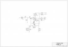
The 1uF cap looks like Cin, but where is Rin, the resistor connect the +ve input to ground? Did you measure the DC voltage at the output pin?
Please read LM3886 datasheet Fig1 to see the +ve input arrangement. Cin should be connected to the "input". If you don't use a pot, Rin may be replaced by a fixed resistor. I hope this will solve your problem.😱
I'm a bit unsure of what you mean, could you maybe draw it for me?
And the output measures -5.5V with ground as reference.
Regards,
Simon H.A.
And the output measures -5.5V with ground as reference.
Regards,
Simon H.A.
Okay I give up.
It can only be the chip that there are something wrong with since I just took it from an old PA box.
Thanks for all your help everybody.
I will now wait for my TPA3122's that will arrive tomorrow and start building a class-d amp.
Regards,
Simon H.A.
It can only be the chip that there are something wrong with since I just took it from an old PA box.
Thanks for all your help everybody.
I will now wait for my TPA3122's that will arrive tomorrow and start building a class-d amp.
Regards,
Simon H.A.
simon, the chip is probably ok, the layout too. Your schematic is wrong! Solder a 47k resistor from pin 10 LM3886 to ground.
Regards
Regards
Hi,
I am sorry for reopening the topic, I am completely new on electronics and I just ordered a Gainclone from China, the power bridge arrived with a capacitor dismounted so I soldered it and it seems working now.
I connected one channel very fast to test the amp and it seems to works but after few secs the sound stop, the only thing I did not connect is the Bridge and the amp board ground so I wondered if this is the issue.
Thank you in advance for your support!
- Status
- Not open for further replies.
- Home
- Amplifiers
- Chip Amps
- LM3886 works in a few seconds then it shut off.