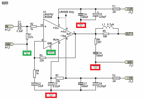
I had an old transformer and got a pair of free lm3886 so I decided to build a chipamp. After doing a little of reading I decided to build the following amp:
And as I´m quite cheap, I decided to do point to point soldering. I finished 1 channel and decided to test it. To test I used ~+-20VDC.
Shorted the input and looked for DC in the output, my cheap meter had moving values and the max was ~4mV.
So I connected a crappy speaker and a source, got music. Then I realized that the lead of C4 was not connected to ground, so I disconnected the speaker and the source, shorted the input and connected the lead of C4 to ground (all grounds together) and after a few seconds I see smoke and the joint of C4 and R6 melts!
I tried again and got the same result. If I do not connect the lead of C4 to ground it "works", but if I connect it, it gets real hot, real fast. I rechecked the solders/wires and see no shorts.
Does any of you have any idea on what could cause this?
An externally hosted image should be here but it was not working when we last tested it.
And as I´m quite cheap, I decided to do point to point soldering. I finished 1 channel and decided to test it. To test I used ~+-20VDC.
Shorted the input and looked for DC in the output, my cheap meter had moving values and the max was ~4mV.
So I connected a crappy speaker and a source, got music. Then I realized that the lead of C4 was not connected to ground, so I disconnected the speaker and the source, shorted the input and connected the lead of C4 to ground (all grounds together) and after a few seconds I see smoke and the joint of C4 and R6 melts!
I tried again and got the same result. If I do not connect the lead of C4 to ground it "works", but if I connect it, it gets real hot, real fast. I rechecked the solders/wires and see no shorts.
Does any of you have any idea on what could cause this?
Probably your amp is oscillating big way.
When you connect the capacitor, the series resistor becomes a load and overheats.
When you connect the capacitor, the series resistor becomes a load and overheats.
It is possible that the LM3886 goes into oscillation. Also you are missing a capacitor 220 pf between pin 9 and 10. It is use to prevent oscillation. Did you check the cap to be good?
Thanks for the replies, I did test with another cap in C4 and saw the same problem. The amp is project 19 in esp's web site: Single Chip 50W Stereo Amplifier
I think you should double check all the connections since you are wiring the amplifier point to point. Ii is easy to miss a problem. I already built one LM3886 and didn't have any problem. I am using my own board. My advice it is to make a copy of the schematic and check it by marking the schematic as you go checking the wiring.
I'm suspecting my grounding. I need to check how to separate the signal and power grounding properly.
It's most likely oscillating because you "connected all grounds together." The low signal (input, feed back network and pin 7 ground) and high current grounds (power by-pass caps and speaker return) must be connected to the power supply common ground separately to prevent the large currents from causing a voltage drop variation in the small signal paths.
Mike
Mike
If you keep it "working" like that you will likely destroy the speaker.
So welcome to the "separating grounds club" 🙂). Separate signal and power grounds and you should be ok. (not completely! they will still meet in the power supply probably)
So welcome to the "separating grounds club" 🙂). Separate signal and power grounds and you should be ok. (not completely! they will still meet in the power supply probably)
It seems that you get an oscillations.Best to check with the scope. Get rid of R6 and C4. These can be the reason for oscillations.
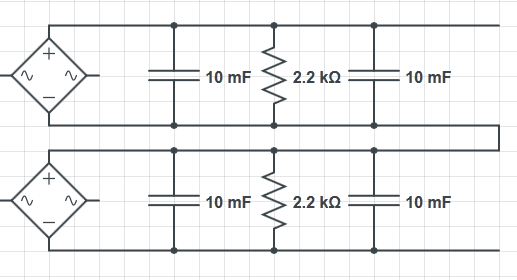
As requested, this is the PSU:
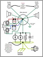
Would the grounds be ok like this:
Would the grounds be ok like this:
Attachments

Last edited:
I think red means points joined together and grounded through one (red?) wire, and green another similar net, using another (green?) wire.
I find the most "dangerous" return the speaker ground, and it always deserves its own dedicated wire, straight to the filter caps junction or the negative if single supply, because of 2 very good reasons:
1) it carries a lot of current and
2) it's audio, in phase with signal, and thus "excellent" to get positive feedback, instability and oscillation. 😱
Or at least weird unexplained distortion.
Correct, the green is intended as signal ground and the red as power ground.
I was checking in Elliot's page for his other implementation of the amp (Project 115) and noticed that the cap and resistor in pin 9 are inverted and the cap is a polar electrolytic.
In the project I built (Project 19) it is shown as a non polar electrolytic.
I also checked other amp diagrams (chipamp.com and some others found with google) and it seems like the cap for pin 9 should be a polar electrolytic with the + side pointing towards the chip. Could you confirm that?
I was checking in Elliot's page for his other implementation of the amp (Project 115) and noticed that the cap and resistor in pin 9 are inverted and the cap is a polar electrolytic.
An externally hosted image should be here but it was not working when we last tested it.
In the project I built (Project 19) it is shown as a non polar electrolytic.
I also checked other amp diagrams (chipamp.com and some others found with google) and it seems like the cap for pin 9 should be a polar electrolytic with the + side pointing towards the chip. Could you confirm that?
The RC in the feedback loop are in series, so order is not important.
The capacitor "should" be a bipolar or NP one, you are right, but a common prctice is to use a cheap polarized one there.
Why?
Because usually its value is quite large, so little peak voltage develops across it in normal use.
If it's less than 1 V under any circunstances, you are fine.
That's why the RC constant which defines the low frequency end must be the one at the input.
If not, you need a bipolar.
Well, I guess I should have used a kit 😛
I changed the grounding and still have problems, as soon as I connect that leg the DC goes from less than 4mV to anything from 9 to 190mV.
I changed the grounding and still have problems, as soon as I connect that leg the DC goes from less than 4mV to anything from 9 to 190mV.
I fixed it! It was a grounding problem. Checked a couple of point to point builds in the forum, notably http://www.diyaudio.com/forums/blogs/wintermute/134-construction-p2p-lm3886-gainclone-part-1.html and realized that I had the feedback cap ground tied to the "zero volts" ground.
So based on wintermute's build, I moved the feedback cap lead to pin 7 and now I can turn it on with everything grounded and measure less than 1mV with no load.
I ventured to connect a source and a speaker and got music 😀
That makes me happy, as you can notice this is my first amp build and now I can move to the other channel.
- Status
- Not open for further replies.
- Home
- Amplifiers
- Chip Amps
- LM3886 with some problems