Some years ago I built two mono LM3886 power amplifiers but untill now I didn't use them. I decided to change my old amplifiers, self designed and built in the late 70's, for these ones. I am suprised by the amazing sound quality coming out of my two Audio Physic speakers (4 ohm).
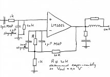
The small modification is quite simple. I omit the electrolytic capacitor in the feedback loop. Then there will be a bias voltage on the output. I compensate this by a resistor to the negative input of the LM3886, with parallel a MKP and a styroflex capacitor. See the circuit.
The resistor will be first a trimming resistor, to find the value so that the output bias voltage will be 0,00 volt. Then replace it by a fixed resistor of the most nearby value.
I also omit Rf2, Cf and Cc, as seen in many applications, because they cause oscillations in the flanks of a square wave by a capacitive load.
I have no time to compare this circuit to the “normal one”. Will somebody do so?

In my case, I've just left that electrolytic cap out of the NFB path, and V out still on range ~ 10mV
In my case, I've just left that electrolytic cap out of the NFB path, and V out still on range ~ 10mV
Ditto. I you balance the DCR at both inputs there will be minimal DC on the output.