Hello, I want to create an amplifier based on the LM3886 chip.
I have some questions about it.
If “gain=20”: “R2” should be equal to “R1x19” for non-inverting.
But I can use for example:
R1 = 1 Ohm; R2 = 19 Ohm
R1 = 10 Ohm; R2 = 190 Ohm
R1 = 100 Ohm ......
It is preferable to use big or small values?
Sorry for my really really poor English
I have some questions about it.
If “gain=20”: “R2” should be equal to “R1x19” for non-inverting.
But I can use for example:
R1 = 1 Ohm; R2 = 19 Ohm
R1 = 10 Ohm; R2 = 190 Ohm
R1 = 100 Ohm ......
It is preferable to use big or small values?
Sorry for my really really poor English
Hi Alex
i think you will find your choice of resistors will depend on the input impedence you require. also if the value or R1 is too large it has more chance of picking up noise.
Regards Ian
i think you will find your choice of resistors will depend on the input impedence you require. also if the value or R1 is too large it has more chance of picking up noise.
Regards Ian
Hi,
See LM3886 data sheet on Nationals web site.
If you don't know how to calculate a value for the design use the application note.
R1 = 1K
R2= 20K
This won't give exactly a gain of 20 but it is close enough and the values are available.
If you use a small R1 the current through it will be very large so it will need to be a power resistor. So I wouldn't use anything much less than 1K for R1.
Andrew
Hi Alex
i think you will find your choice of resistors will depend on the input impedence you require. also if the value or R1 is too large it has more chance of picking up noise.
Regards Ian
When I say "R1", I'm talking about "Ri"
An externally hosted image should be here but it was not working when we last tested it.
In this application, Ri change the input impedance ? 😕
What is the utility of Rb (1KOhm) ?
I think "RL" is the speaker ? "Rin" is a pot ?
There is, as always, a tradeoff here. Low values cause high currents. High values cause high noise. Resistor values near the datasheet values give a reasonable compromise. Keep Ri = 1k, for instance, and chose the other resistor value to give the gain you need.
Hi,
do not use that National schematic.
Many of the optional components are omitted.
Use ALL the optional components and build an AC coupled amplifier not a DC coupled amplifier nor a mixed AC & DC coupled amplifier.
do not use that National schematic.
Many of the optional components are omitted.
Use ALL the optional components and build an AC coupled amplifier not a DC coupled amplifier nor a mixed AC & DC coupled amplifier.
if Ri=1x and Rfl=20x and Rb=1x and Rin=20x, then the overall gain is 20times (+26dB). (Rin has been omitted from the schematic, another bad bit of advice from National).
Note, I have not attached ohms to any values, I am simply quoting resistor ratios.
The chipamp gain is 1+ {20x/1x} = 21times (+26.44dB)
Note also that Ri & Ci control the chipamps bass performance. Ci should be sized so that virtually no AC signal ever appears across it. If Ri is low value than that low AC voltage condition requires Ci to be very large in value, tens of mF!
Hi,
do not use that National schematic.
Many of the optional components are omitted.
Use ALL the optional components and build an AC coupled amplifier not a DC coupled amplifier nor a mixed AC & DC coupled amplifier.
Many Gainclone schematics works like the National schematic !
Sure they do, but if you make a DC coupled amplifier like the one shown, without DC correction (servo) and DC detection/protection on the output, you are very likely to fry speakers. Or you could just build an AC coupled amp like AndrewT is suggesting, since it's easier and cheaper.
Ok thank you, maybe I’m going to make the amplifier without the capacitor.
If I have a very high DC offset, I will add the capacitor.
What is the max value for the DC offset?
I'm don't want any capacitor because I’m trying to make an amp with less parts as possible.
Sorry for my poor english.
If I have a very high DC offset, I will add the capacitor.
What is the max value for the DC offset?
I'm don't want any capacitor because I’m trying to make an amp with less parts as possible.
Sorry for my poor english.
QUOTE
What is the max value for the DC offset?
hello.
....often not more than +-100mv dc at the output of the opamp is recommended.
you can increase the 680 ohm res in the feedback to 1k if you like that,this can help a little bit if the offset is to high.
greetings
What is the max value for the DC offset?
hello.
....often not more than +-100mv dc at the output of the opamp is recommended.
you can increase the 680 ohm res in the feedback to 1k if you like that,this can help a little bit if the offset is to high.
greetings
I have made a new schema for my gainclone
I still don't know what the "RB" resistor is used for 😕
I have read that "Rm" resistor can affect the gain, is it true ?
I still don't know what the "RB" resistor is used for 😕
An externally hosted image should be here but it was not working when we last tested it.
I have read that "Rm" resistor can affect the gain, is it true ?
If I have a very high DC offset, I will add the capacitor.
It's not just about the amplifier's DC offset. If you have no input capacitor and no feedback capacitor, your amplifier will amplify the DC offset of your source by whatever your gain is. If someone comes along and plugs in a source you haven't tested, and it has 100mV of offset, you are suddenly putting 2.6V of offset into your speakers.
I have made a new schema for my gainclone
I still don't know what the "RB" resistor is used for 😕
From the excellent datasheet:
http://www.national.com/ds/LM/LM3886.pdfPrevents currents from entering the amplifier’s non-inverting input which may be passed through to the load upon power-down of the system due to the low input impedance of the circuitry when the under-voltage circuitry is off. This phenomenon occurs when the supply voltages are below 1.5V.
In other words, limits thumping noises when switching off the amp.
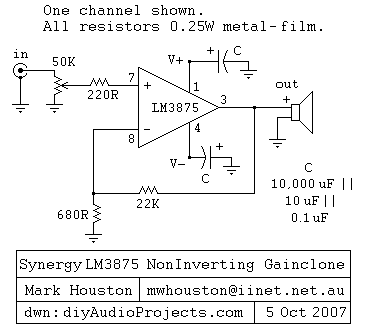
Regarding gain-setting resistors: 680 ohm is another popular value for Ri, as shown in the Synergy circuit diagram. That is another reasonable compromise between current (=heat) and noise.
It's not just about the amplifier's DC offset. If you have no input capacitor and no feedback capacitor, your amplifier will amplify the DC offset of your source by whatever your gain is. If someone comes along and plugs in a source you haven't tested, and it has 100mV of offset, you are suddenly putting 2.6V of offset into your speakers.
My preamp already have ouput capacitors.
In other words, limits thumping noises when switching off the amp.
I don't care about that.
National says that a high feedback resistors value can reduce the DC Offset. I think I will try with diffenrents values (20K, 40K, 60K, 80K). National recommend a resistor between 10K and 100KOhm.
hello.
in the data sheet page 8 there is an external parts description.
rb can work as a rf-attenuator if you solder it nearby or close to the input pin of the opamp (analogous with tubes called grid res,with mosfet called gate res).
you should build in a res from signal input to ground (perhaps 100k or so) if you leave out the pot .so that the input is (dc-way)closed.
greetings
Thank you for all your help
I will buy all the optional components, and put them only if it necessary.
I'm now thinking about the power supply
I have 70W - 6 ohm speakers, so according to the datasheet, I need 32-33VCC.
24VAC*1.414 = 34VCC
But I think I have some loose due to the rectifier and the capacitors, so I have to take a 30VAC transformer?
Sorry for my poor English.
25Vac to 28Vac for 8ohm speakerBut I think I have some loose due to the rectifier and the capacitors, so I have to take a 30VAC transformer?[/FONT][/COLOR]
22Vac to 24Vac for 6ohm speaker
18 to 21Vac for 4ohm speaker and for 4 to 8ohm speaker.
Do not use 30Vac for any speaker loading.
These are all dual secondary voltages, i.e. 25Vac is 25-0,25-0Vac dual secondary transformer or 25-0-25Vac Centre Tapped transformer. The Centre tapped is sometimes seen as; 50Vac Centre Tapped. Be sure you know which you are ordering.
25Vac to 28Vac for 8ohm speaker
22Vac to 24Vac for 6ohm speaker
18 to 21Vac for 4ohm speaker and for 4 to 8ohm speaker.
it is written in the datasheet? 😕
The datasheet gives the +-Vdc and the |+Vdc| + |-Vdc| values, both in specification and in the plots/graphs. (mod X = |X|)
The transformer voltage can be converted to DC voltage using this formula.
DCvoltage ~ Mains supply voltage / Rated Input voltage * rated output voltage * 1+regulation * sqrt(2) +-manufacturing tolerance - Vdrop of rectifier.
For worst case maximum voltage in the UK where we have a 240Vac supply with limits of 216 to 254Vac a 230:25+25Vac transformer with 7% regulation passing through one bridge rectifier
Max DC voltage = 254 / 230 * 50 * 1.07 * 1.414 - 1.0 +-tolerance ~ 82.5V+-tol
The dual polarity voltage will be ~+-41Vdc. Maximum worst case DC voltage is just inside the 84V limit for a 3886 chipamp. This is too high for a 6ohm and for a 4ohm speaker.
english correction:
is it written in the datasheet?
The transformer voltage can be converted to DC voltage using this formula.
DCvoltage ~ Mains supply voltage / Rated Input voltage * rated output voltage * 1+regulation * sqrt(2) +-manufacturing tolerance - Vdrop of rectifier.
For worst case maximum voltage in the UK where we have a 240Vac supply with limits of 216 to 254Vac a 230:25+25Vac transformer with 7% regulation passing through one bridge rectifier
Max DC voltage = 254 / 230 * 50 * 1.07 * 1.414 - 1.0 +-tolerance ~ 82.5V+-tol
The dual polarity voltage will be ~+-41Vdc. Maximum worst case DC voltage is just inside the 84V limit for a 3886 chipamp. This is too high for a 6ohm and for a 4ohm speaker.
english correction:
should be:it is written in the datasheet?
is it written in the datasheet?
- Status
- Not open for further replies.
- Home
- Amplifiers
- Chip Amps
- LM3886 question.