Hi,
First I'd like to say thanks to everyone that's contributed to this forum. I've learned so much since starting on this project.
My plan is to build a two channel chip amp with the LM3886, powered from a single unregulated power supply.
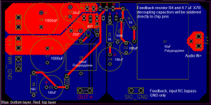
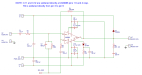
I read somewhere that a two layer PCB with split ground planes for the power ground and signal ground work well, so that is how I based the design. The schematic is based on ApexAudio's gainclone, modified slightly with some recommendations I found here on diyaudio.
After researching various grounding schemes, I learned that I could take the input ground and speaker grounds directly to the main audio ground on the chassis, so the signal ground plane in this PCB only connects the feedback loop and the input RC bypass circuit.
Will that work? I'm a little confused in this area because most PCB's I've seen have the input ground, speaker ground, and power ground coming together on the amp PCB.
If anyone would like to give feedback on this design, tell me what's wrong with it, or ways to improve it, I would really appreciate it.
First I'd like to say thanks to everyone that's contributed to this forum. I've learned so much since starting on this project.
My plan is to build a two channel chip amp with the LM3886, powered from a single unregulated power supply.
I read somewhere that a two layer PCB with split ground planes for the power ground and signal ground work well, so that is how I based the design. The schematic is based on ApexAudio's gainclone, modified slightly with some recommendations I found here on diyaudio.
After researching various grounding schemes, I learned that I could take the input ground and speaker grounds directly to the main audio ground on the chassis, so the signal ground plane in this PCB only connects the feedback loop and the input RC bypass circuit.
Will that work? I'm a little confused in this area because most PCB's I've seen have the input ground, speaker ground, and power ground coming together on the amp PCB.
If anyone would like to give feedback on this design, tell me what's wrong with it, or ways to improve it, I would really appreciate it.
Attachments
Probably best to just use the LM3886 datasheet schematic. It has some good info on layout as well.
Tomchr website and his threads on Diyaudio are a very good source of information on designing a LM3886 layout.
Analyzing the layout of the Audiosector/Chipamp.com boards may also be helpful in designing your own.
Tomchr website and his threads on Diyaudio are a very good source of information on designing a LM3886 layout.
Analyzing the layout of the Audiosector/Chipamp.com boards may also be helpful in designing your own.
As I stated in your other Thread:
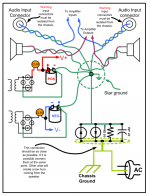
throw that wiring diagram in the bin.
Read Bonsai's amplifier wiring pdf.
throw that wiring diagram in the bin.
Read Bonsai's amplifier wiring pdf.
????the main audio ground on the chassis
The Protective Earth is directly connected to Chassis.
This is a SAFETY connection that has absolutely nothing to do with Main Audio Ground.
The Chassis is your enclosure that attenuates interference, when correctly implemented.
An additional requirement is that all exposed conductive parts should be connected to the protected Chassis.
This too is a SAFETY requirement and has nothing to do with Main Audio Ground.
Last edited:
C1 is probably too big for the range of signals you require to be amplified.
C4 is too small to properly amplify the LF range of signals you may want to hear.
Your grounding analysis is quite confused. You need to rethink that.
C4 is too small to properly amplify the LF range of signals you may want to hear.
Your grounding analysis is quite confused. You need to rethink that.
Last edited:
????
The Protective Earth is directly connected to Chassis.
This is a SAFETY connection that has absolutely nothing to do with Main Audio Ground.
The Chassis is your enclosure that attenuates interference, when correctly implemented.
An additional requirement is that all exposed conductive parts should be connected to the protected Chassis.
This too is a SAFETY requirement and has nothing to do with Main Audio Ground.
Ok, thanks for clearing that up, I think I understand- the main audio ground should connect to the protective earth, and the protective earth connects to the chassis.
As I stated in your other Thread:
throw that wiring diagram in the bin.
Read Bonsai's amplifier wiring pdf.
Ok done... But what's wrong with it?
Your grounding analysis is quite confused. You need to rethink that.
Do you mean the ground planes or the wiring diagram? Could you elaborate some more?
That is not what is required.Ok, thanks for clearing that up, I think I understand- the main audio ground should connect to the protective earth, and the protective earth connects to the chassis.
The Main Audio Ground is there to do an audio duty.
No amplifier requires an enclosure to operate as an audio amplifier.
The PE and Chassis are only there for SAFETY reasons. They are not audio !
I gave an answer already in that other Thread.Ok done... But what's wrong with it?
There are dozens of Members here who repeatedly give the same information. Read it.Do you mean the ground planes or the wiring diagram? Could you elaborate some more?
Read Bonsai, read D.Self, read W.Jung, read ESP, read R.Cordell.
I gave an answer already in that other Thread.
Oh, I just saw that. Thanks for the info, I just found the wiring guide by Bonsai
Actually the Bonsai diagram isn't all that great either. It's basically star ground with a large impedance between the power ground and the reference ground. That's not so hot if you're looking to reproduce the data sheet performance of the LM3886.
I'd scrap the wiring diagram with the star ground. Your PCB layout is not bad. It could be improved, but it's not bad. Specifically, I would beef up the output trace and join the reference ground to the power ground at the speaker return/ground connection. D2 is not needed. R5 should go to V-. You'll likely get lower THD by routing C4 to the power ground. It looks like you forgot Cc, Rf2, and Cf (see page 8 of the LM3886 data sheet).
Tom
There are dozens of Members here who repeatedly give the same information. Read it.
Read Bonsai, read D.Self, read W.Jung, read ESP, read R.Cordell.
You forgot T.Christiansen. 🙂
Specifically: Taming the LM3886 Chip Amplifier
Tom
Actually the Bonsai diagram isn't all that great either. It's basically star ground with a large impedance between the power ground and the reference ground. That's not so hot if you're looking to reproduce the data sheet performance of the LM3886.
The Bonsai wiring diagram shows the input ground/signal ground connecting to the power ground on the amp PCB via a 15 ohm resistor. Is there any advantage in doing it this way versus taking the input ground and signal ground directly to the main audio ground?
It looks like you forgot Cc, Rf2, and Cf (see page 8 of the LM3886 data sheet).
Tom
I excluded Cc because I read a couple comments that said never to put a cap between the two inputs. I also read that Rf2 and Cf weren't really necessary (I think AndrewT said in another thread to first try without them). Would you recommend that I include these components? What effects do Rf2 and Cf have on sound quality?
The Bonsai wiring diagram shows the input ground/signal ground connecting to the power ground on the amp PCB via a 15 ohm resistor. Is there any advantage in doing it this way versus taking the input ground and signal ground directly to the main audio ground?
No. There is no advantage. You introduce whatever error voltage forms across that 15 Ω resistor into the signal path. Not the desired mode of operation. You're better off with a 0 Ω connection. You get this by using as wide and short a connection as you can get (hint: ground plane/pour).
I excluded Cc because I read a couple comments that said never to put a cap between the two inputs.
That may be a good rule of thumb for most op-amps, but isn't a good rule for the LM3886. You can convince yourself of this pretty easily by building the circuit without Cc and running a sine wave into the amp. Crank up the amplitude to a few volt below clipping. You'll notice a buzz on the output waveform as the output approaches the rail voltage. Add Cc and the buzz goes away but now the transient response is dorked up. Add Rf2 and Cf to deal with this.
I also read that Rf2 and Cf weren't really necessary (I think AndrewT said in another thread to first try without them). Would you recommend that I include these components? What effects do Rf2 and Cf have on sound quality?
If you use Cc, Rf2 and Cf are necessary if you want a clean transient response. If you go without Cc, Rf2 and Cf are not necessary.
Tom
He'll have a hard job searching T.Chrstiansen.
He needs to search "Tomchr". That's your unique name on this Forum.
Timchr,
do you have a view on removing the not connected pins?
I'm thinking about making it a bit easier to route traces to the used pins.
do you have a view on removing the not connected pins?
I'm thinking about making it a bit easier to route traces to the used pins.
C1 is probably too big for the range of signals you require to be amplified.
C4 is too small to properly amplify the LF range of signals you may want to hear.
How can I determine the correct values for these components?
Timchr,
do you have a view on removing the not connected pins?
I'm thinking about making it a bit easier to route traces to the used pins.
Do you feel that's better than connecting the unused pins to the power traces?
- Status
- Not open for further replies.
- Home
- Amplifiers
- Chip Amps
- LM3886 PCB Layout with Split Ground Planes?