I will have to change my PCB design radically when using resistors with such packages 🙂
Maybe you can adapt it bending leads.
What kind of sound does it have?
No particular sound, it sound just like cement wire resistors, only more detailed with little or no harshness.
BTW, the main point is that those resistors are non inductive, if you mind about that. 😉
No, best to change the design while it is still possible. I want to make it as versatile as possible within my ability.Maybe you can adapt it bending leads.
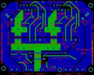
I changed the PCB design so it can house up to three parallel resistors, but I can also use the Caddock's now 🙂 . I attached a image of the current design. The large green traces are the outputs to the speaker. The signal path's to and from the the LM3886's are exact copies.
I will try some different types and brands when I got the amp up and running.
These Welwyn resistors where also recommended to me elsewhere. They should be good value for money.
Attachments
those welwyn are 5% tolerance.
You will have to match them to get the 1% requirement.
Easier and cheaper to use 1% metal film.
You will have to match them to get the 1% requirement.
Easier and cheaper to use 1% metal film.
using the 3pairs of pads, you could insert 6 resistors, 3 on the top and 3 on the bottom.
or
insert thick copper leads from the top and add 3 resistors to each pair of upstanding leads for a 9 parallel resistor network.
or
lots of ways to use the small 600mW metal films.
or
insert thick copper leads from the top and add 3 resistors to each pair of upstanding leads for a 9 parallel resistor network.
or
lots of ways to use the small 600mW metal films.
MP930 are very good resistors, expensive but excelent SQ.
@Corpius, caddock makes various tolerance, check before buy...
also check the heathsink dimensions, a litle change in pads position may be necessary.
ciao.
@Corpius, caddock makes various tolerance, check before buy...
also check the heathsink dimensions, a litle change in pads position may be necessary.
ciao.
@Andrew
Thanks for pointing that out. I don't want to be left with a bunch of resistors that could not be matched, so they're removed from my list.
@bicefalo
I put those on the list already. I will check the tolerance before buying them. Thanks!
I have to do some more ckecks to be sure I made no mistakes in the design before I send my Gerber files to the PCB manufacturer. I don't want to waste my money on a faulty design 🙂
Corpi,
build up a two transistor CCS at 190mA.
Passing this current through a string of low value resistors allows you to accurately compare the voltage drop across each resistor.
The string could be 10 off 1r0 or 20 off 0r5 or ......, for a total resistor voltage drop of 1.9V
Add on ~3.1V for the CCS and use a 5V supply.
Try to get the voltage drop across the CCS after it has warmed up to the same value for each set of tests. That allows a fairly repeatable constant current for the measurements.
You could add a very accurate dummy resistor (0.1% 1r0) in the string that becomes your REF voltage value for better repeatability.
I assemble the string into two sets of insulated terminals strips with the resistors running zig zag between the strips. If the terminal strips are parallel then all the leads ends MUST be the same length and thus the SAME lead end resistance.

I'm not sure if you're running simulations (or just drawing circuit diagrams) but any how,
like that other chap said "that circuit has a 220pF between the inputs of the chip. I found when I removed that capacitor, amazingly all that harshness at the top end disappeared."
if you are doing simulations try one as it is and watch for rising gain over maybe 40khz, then ditch the wee caps and see what happens
if you wanted to roll off the higher frequency some ground the capacitor instead of connecting to the inverting input
I reckon you can go as high as 470pf
you'll hear this more than you will resistors
Probably going against the crowd here, but....
IMO, the value of the output resistors is too low unless extreme care is taken to match the gains of the chips.
E.g. Lets assume the resistors are as shown, 3*0.5R in parallel per side, and lets also assume 1% resistors are used in the feedback networks, giving a worst case difference of 4% between the gains of the two chips.
Now with 1V in and 23Vout and no load, there's a 0.92V difference between the outputs of the two chips, causing 2.76A of current to flow between them through the resistor.
OK, it probably won't damage anything but I wouldn't want the chips working that hard before you even connect the speaker.
With an 8 Ohm load connected, the current through the load would be 2.84A, comprised of 4.18A from one chip and -1.34A from the other. So much for equal current sharing! The only time the second chip will actually contribute something positive is when the first chip's protection circuitry kicks in.
Forget the noise of the output resistors. The noise they contribute is a couple of thousand times lower than the noise contributed by the resistors at the input and in the feedback network. (and the noise caused by those resistors is inaudible anyway; almost -100dB re 1 Watt)noise
Does the tolerance really matter? The worst possible case with 5% resistors is an imbalance of 10% between left and right channels i.e. 16mΩ difference in output impedance.those welwyn are 5% tolerance.
You will have to match them to get the 1% requirement.
Easier and cheaper to use 1% metal film.
IMO those 220pF caps should be removed. All they so is compromise the high frequency stability, adding an extra pole at about 370KHz to the feedback loop."that circuit has a 220pF between the inputs of the chip. I found when I removed that capacitor, amazingly all that harshness at the top end disappeared."
if you are doing simulations try one as it is and watch for rising gain over maybe 40khz, then ditch the wee caps and see what happens
I have never fitted a cap direct to the -IN pin, because all the good literature tells me that only in a very few specific compensation arrangements does the added cap work.......................like that other chap said "that circuit has a 220pF between the inputs of the chip. I found when I removed that capacitor, amazingly all that harshness at the top end disappeared."................
In most arrangements adding a cap to the -IN pin introduces less stability.
So I cannot compare the wrong way to do it with the correct way to do it.
I have said many times that the RF input filter be connected to Signal Ground.
How many more times does that need to be repeated?
I have also repeatedly suggested that an extra RF cap be placed across the input socket. That too gets ignored by the majority of the Membership.
Does anyone read what is put out there?
Possibly not, but it comes from the National datasheet.............................
Does the tolerance really matter? The worst possible case with 5% resistors is an imbalance of 10% between left and right channels i.e. 16mΩ difference in output impedance.......................
It's one of the reasons I have never implemented any of the paralleled and/or bridged chipamps.
The compromises introduced by the P & B implementations requires much design input from the builder. and a lot of snagging knowledge to identify the problems that were not identified at the design stage.
Fully agree with both analysis.
Paralleling practically perfect voltage sources is a dumb idea, unfortunalely suggested by a respected manufacturer who should know better and warmly embraced by noobs who aren't happy with what the chip amp can put out (which is more than enough) and on the other side can't design their own beefier amp.
Having 2 stupid but stubborn "brains" (both amps and their NFB networks) fighting over what voltage should be present at the output and happy to supply any current needed to achieve that end is nonsense.
As of input filtering, FWIW I *always* fit 2 caps: 1 across the input, from hot to ground and another across the first BE junction *or* + to - inputs if said junction is not externaly available.
My amps have worked flawlessly on stages where others (famous brands, by the way) have become unexpected radio receivers .... with embarrassing results many times.
As does that never-to-be-sufficiently-cursed idea of putting a cap between the input pins.Possibly not, but it comes from the National datasheet.
🙁
Does the tolerance really matter? The worst possible case with 5% resistors is an imbalance of 10% between left and right channels i.e. 16mΩ difference in output impedance.
if you care enough about the tolerance's to be discussing it then it's probably and issue worth spending some time on. In the past I have bought the cheaper lower tolerance (carbon) resistors (more than I actually need) and then check the actual values with a (digital) meter and finally (for instance) use the closest pair in a stereo setup.
being a parallel design your going to want to all the values you can control as close to matching as you can. It's the (negative) feedback resistors that will need to be really bang on.
and I agree with the other guys, parallel (gain clones) is a bad idea, spend your money elsewhere, bigger transformers or dual instead of single, more supply caps and if that still isn't enough think about going to a transistor output design.
In their application notes they specify Dale resistors, for some of the later circuits at least. I've herd it said that carbon resistors "sound" better, it would be interesting to do some actual double blind testing with otherwise identical amps. but that's kind of an aside....
I try to, but Mr. time won't let me. There's simply too much to read 🙂Does anyone read what is put out there?
I'm still a noob when it comes to electronics, but I'm willing to learn. So parallel gain clones are a bad idea, unless I can get it all bang on. I'll do some more research about the benefits of a single chip amp compared to a paralleled one.
Hi,
Lately I have been gearing up to imbark on a parallel design too.
I have done a lot of reading and it seems to be more beneficial to employ a D.C. servo circuit when it comes to paralleling of such devices.
I know it cost more but IMO the performance gains seem to out weigh this cost as well as solving the offset issue.
Many seem to feel that paralleled chip amps are a waste of components.
My goal is not to have an increase of power output but to have a stable amp that can operate well into the 1 to 2 ohm range as my voltage swing requirements are of about 20Vpeak and not much more than 30Vpeak or so max.
I will start with a 2X model first as well and then proceed to a 4X one as this should meet my goals.
After that I may try to bridge them should I find that I do need a higher voltage swing.
Here are two very good threads on this matter,
http://www.diyaudio.com/forums/chip-amps/153501-lm3886-x-2-parallel.html#post1952598
This one is more about the D.C.servo's and shows some great examples with discussions as to why some configurations may be better than others,
http://www.diyaudio.com/forums/chip-amps/166722-problem-parallel-lm3886-pa-100-a.html#post2183632
There is one other very good thread on this matter that is basically a follow up on the second link but I haven't taken the time to find it yet.
It goes into more detail of a very large paralleled chipamp setup using the techniques described in the previous thread that I posted.
FWIW
jer 🙂
A single chipamp can be a a really good amplifier if you don't run it into clipping, neither voltage clipping nor current clipping.
If more SPL is required there are two routes and they can be combined.
Higher efficiency speaker
and/or
Higher power from a different and more suitable topology.
PA100, BA100, BPA200 and BPA300 are there to allow National to sell more chips to the demented Members that just burnt up their previous implementation of their multi chip amplifiers.
National's LME498xx etc can go to much higher powers and still keep much of the attraction (simplicity) of the chipamp.
Given my ignorance and after reading almost the whole evening about bridged or parallel chipamps I'm convinced that I'd better start on a single chipamp design 🙂 Back to the drawing board.
One question regarding the zobel networks.
At Decibel Duncan's site I see that he is only using a 0R22 output resistor and a Zobel network that consists of a 2R7 resistor and a 100nF film cap.
When I look at other designs I also see inductor + resistor networks. Sometimes only even both, like at Rod Elliots pages or the LM3886 datasheet.
Image from ESP:
Is it OK use a 0R22 output resistor followed by a zobel network consisting of a 2R7 resistor and a 100nF film cap or is is best to include the inductor + resistor?
@Andrew:
Your Thiele network calculator shows even another network.
I thinks that I'm a bit lost in the woods now.
A year ago I read some posts on how to make your own inductor (number of windings, wire diameter, etc.), but I can't find it anymore. I just found this calculator to calculate the number of windings to get the desired inductance.
CalCoils Inductance Calculator
Is the calculator correct?
I have some enameled soft copper wire (1.5 mm) lying around, so I'd like to give it a try and make my own 0.7uH inductors. I have no way measuring the true inductance after making my own inductor, but maybe the workshop at my work can help me out. 🙂
One question regarding the zobel networks.
At Decibel Duncan's site I see that he is only using a 0R22 output resistor and a Zobel network that consists of a 2R7 resistor and a 100nF film cap.
When I look at other designs I also see inductor + resistor networks. Sometimes only even both, like at Rod Elliots pages or the LM3886 datasheet.
Image from ESP:
An externally hosted image should be here but it was not working when we last tested it.
Is it OK use a 0R22 output resistor followed by a zobel network consisting of a 2R7 resistor and a 100nF film cap or is is best to include the inductor + resistor?
@Andrew:
Your Thiele network calculator shows even another network.
I thinks that I'm a bit lost in the woods now.
A year ago I read some posts on how to make your own inductor (number of windings, wire diameter, etc.), but I can't find it anymore. I just found this calculator to calculate the number of windings to get the desired inductance.
CalCoils Inductance Calculator
Is the calculator correct?
I have some enameled soft copper wire (1.5 mm) lying around, so I'd like to give it a try and make my own 0.7uH inductors. I have no way measuring the true inductance after making my own inductor, but maybe the workshop at my work can help me out. 🙂
Thiele showed two output network arrangements to give the HF load that the amplifier needed to see.
If you look at post4 that might explain.
Cherry then realised that Thiele's two networks were at opposite ends of the same infinite series of networks.
My spreadsheet is simply the implementation of Cherry's rule for determining the intermediate network values.
If you set the values as described in my text, the results show either of the Thiele original limit values, one with the RC before the inductor, the other with the cap after the inductor.
BTW
there are many guides to creating low value output inductors on this Forum.
One of mine that I have posted a few times is wind about 8turns on a former about ½" diam. My latest was to use a AA battery as a former. A Member tested a clone of this and it came out at 0.7uH, by luck. I don't think the exact value matters much because at HF it appears as near open circuit and it's the parallel resistor that is providing the load in conjunction with the cap across the speaker terminals. That cap can be a physical device, or it can be the speaker cables attached to the terminals.
I have also posted a spreadsheet with air cored inductor guidance.
Last edited:
- Status
- Not open for further replies.
- Home
- Amplifiers
- Chip Amps
- LM3886 parallel output resistors