ok, what can i do it? I put input to ground and i misure the output voltage with multimeter in VDC (mV) ??Can you measure the output offset voltage foar each board sepparately with inputs shorted to ground?
ok, what can i do it? I put input to ground and i misure the output voltage with multimeter in VDC (mV) ??Can you measure the output offset voltage foar each board sepparately with inputs shorted to ground?
my memory is terrible.
Has anyone asked if both the chipamps' tabs are isolated from the heatsinks?
Has anyone asked if both the chipamps' tabs are isolated from the heatsinks?
oh yeah, i use LM3886 with Plastic Package like LM3886TF...my memory is terrible.
Has anyone asked if both the chipamps' tabs are isolated from the heatsinks?
In addition to measuring the output offset voltage, can you post a picture of the bottom of the board (the side with the copper traces)?
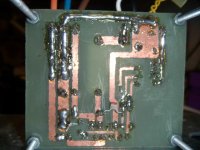
In addition to measuring the output offset voltage, can you post a picture of the bottom of the board (the side with the copper traces)?
is it ok?
Maybe it could be that You do not have the op LF for the auto off-set
?
I think that in the data sheet has been told that in parallel mode,
every modul must have the own one..?
*
And think, that it could be something with z zobel net - out res net also?
cheers
?
I think that in the data sheet has been told that in parallel mode,
every modul must have the own one..?
*
And think, that it could be something with z zobel net - out res net also?
cheers
Maybe it could be that You do not have the op LF for the auto off-set
?
I think that in the data sheet has been told that in parallel mode,
every modul must have the own one..?
*
And think, that it could be something with z zobel net - out res net also?
cheers
scuse me, but what is "op LF for the auto off-set"? i dont know
Sorry,
LF441 (if I am remember well) is the OP amp from PDF datas, for auto-off-set circuit?
please check it...
LF441 (if I am remember well) is the OP amp from PDF datas, for auto-off-set circuit?
please check it...
lf411 is the old and cheap opamp that suits DC servo duty.
There are many newer, expensive and better performing opamps. You need low offset (Vos<1mV) and low change of offset (deltaVos/deltaT<10uV/C) with temperature and with age.
There are many newer, expensive and better performing opamps. You need low offset (Vos<1mV) and low change of offset (deltaVos/deltaT<10uV/C) with temperature and with age.
Zoran probably refers to the optional DC servos shown in application note AN-1192.
where is it?? i can't find it...^_^
http://www.national.com/an/AN/AN-1192.pdf
The DC servos are shown in the BPA-200 section and in a sub-chapter of the schematics section.
The DC servos are shown in the BPA-200 section and in a sub-chapter of the schematics section.
Did someone actually measure the output offset? It should be for the individual amplifiers as well as the paralleled combination, input shorted, load connected.
And can we take a look at the heatsinks? Parallel 3886 generate quite a bit of heat depending on their relative offset and resistor matching. How hot are the heatsinks? If the chip is going into protection before the sinks get warm, you have a thermal transfer issue. I don't see any hints of thermal compound in your construction, even for the TF package like you use, some is absolutely necessary.
One can reduce the anomalies somewhat by using bigger output resistors. I use 2x0.47 ohm resistors in parallel per chip (0.235 ohm), and this still makes the sinks run very warm at idle. It gets better as the power output goes up. Are yours inductive by any chance? Try increasing your 0.1 ohm resistors to 0.22 for a little better stability.
And I would try dropping that 4.7pF feedback cap for a while, as well as the C2 and C5 mentioned by PB. There may be some feedback between output and input, causing oscillation.
Would suggest you try these and report back before building any new circuits.
😀😀😀 thanks you very much, maybe tomorrow i'll try to change the heatsink.... the chips go into protection before the sinks get warm with load and without load (4 ohms).... so, now i'm using a bad heatsink (in iron- alluminium;i think😕😕😕), but its too big, about 30 cms for each LM3886...so, tomorrow,i'll going to buy a serius and good heatsink ...Did someone actually measure the output offset? It should be for the individual amplifiers as well as the paralleled combination, input shorted, load connected.
And can we take a look at the heatsinks? Parallel 3886 generate quite a bit of heat depending on their relative offset and resistor matching. How hot are the heatsinks? If the chip is going into protection before the sinks get warm, you have a thermal transfer issue. I don't see any hints of thermal compound in your construction, even for the TF package like you use, some is absolutely necessary.
One can reduce the anomalies somewhat by using bigger output resistors. I use 2x0.47 ohm resistors in parallel per chip (0.235 ohm), and this still makes the sinks run very warm at idle. It gets better as the power output goes up. Are yours inductive by any chance? Try increasing your 0.1 ohm resistors to 0.22 for a little better stability.
And I would try dropping that 4.7pF feedback cap for a while, as well as the C2 and C5 mentioned by PB. There may be some feedback between output and input, causing oscillation.
Would suggest you try these and report back before building any new circuits.
thanks for the hint, maybe if it doesn't work i'll try to improve Rout value for each LM3886.... i hope to get success!😉😉😉
Are you operating both modules off of 1 +/- 30 volt power supply or 2?
If you are running them off of 2 separate supplys and not powering them up at the same time you may be getting some sort of latchup problem on one or both of the amplifiers. They should be run off of 1 supply with +/- 30v and ground connected in parallel on each module.
If you are running them off of 2 separate supplys and not powering them up at the same time you may be getting some sort of latchup problem on one or both of the amplifiers. They should be run off of 1 supply with +/- 30v and ground connected in parallel on each module.
Are you operating both modules off of 1 +/- 30 volt power supply or 2?
If you are running them off of 2 separate supplys and not powering them up at the same time you may be getting some sort of latchup problem on one or both of the amplifiers. They should be run off of 1 supply with +/- 30v and ground connected in parallel on each module.
i've followed this schematic for power supply.... i use one power supply for 2 LM3886... is it correct?
Attachments
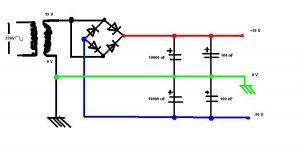
That power supply is a little bit weird but should work, except that with 19 VAC RMS from the transformer, you would probably only be getting a little over +/- 26 VDC for your power rails.
By the way, those 100nF caps could be the subject of a debate. If they are high quality (low ESR, such as film or C0G/NPO ceramic) then they could cause high-frequency ringing.
By the way, those 100nF caps could be the subject of a debate. If they are high quality (low ESR, such as film or C0G/NPO ceramic) then they could cause high-frequency ringing.
Last edited:
- Status
- Not open for further replies.
- Home
- Amplifiers
- Chip Amps
- LM3886 PA100 Problem