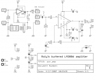
If anyone can still make use of this design, please provide some feedback.
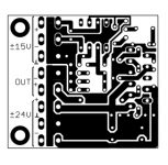
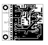
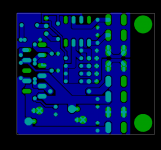
I post low-resolution pictures here, but hi-res data is available.
Next step will be prototyping. Anyone? 😀
Cheers,
Sebastian.
I post low-resolution pictures here, but hi-res data is available.
Next step will be prototyping. Anyone? 😀
Cheers,
Sebastian.
I have not looked closely, but I would say the electrolytic cap package you used is a bit small. I would make it a bit bigger to allow for more flexibility in cap selection. Around 11mm is pretty good choice.
Cheers!
Russ
Cheers!
Russ
Hi Russ,
the original design is intended for use with separate amplifier PSU and preamplifier PSU.
Roly, the thread starter, said he has both. 😉
Cheers,
Sebastian.
PS: You need +/-15V for the opamp, so you need a separate PSU anyway...
the original design is intended for use with separate amplifier PSU and preamplifier PSU.
Roly, the thread starter, said he has both. 😉
Cheers,
Sebastian.
PS: You need +/-15V for the opamp, so you need a separate PSU anyway...
sek said:Hi Russ,
the original design is intended for use with separate amplifier PSU and preamplifier PSU.
Roly, the thread starter, said he has both. 😉
Cheers,
Sebastian.
PS: You need +/-15V for the opamp, so you need a separate PSU anyway...
Thats good to know, but I would still offer the same advice.
Those in the current layout are 8mm devices, i.e. 220uf/35V.
There's room for 11mm caps, but then the film caps would have to go (even farther away from the chip pins). The board shouldn't go larger, and it shouldn't go SMT either.
I thought electrolyte capacitors of higher quality and a set of film caps close to the chip would be superiour to larger bulk caps and no film bypass. Would increasing elco size and moving film caps away be an alternative to try? I just checked a supplier - 220uf/35V caps are available as low ESR type in 10mm cans.
But I honestly think that both ways would sound good and work well with a large-capacitance PSU. 😉
Cheers,
Sebastian.
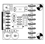
Okay, as per Russ' request I did a version for 11mm capacitor devices.
It features 3.5mm and 5mm pitch holes, the 5mm footprint is rotated 45 degree.
This now opens up the possibility to employ any capacitor size and value up to, say, 470uF/35V.
The original recommendation of 220uF/35V as a low ESR type also features 11mm diameter.
Here goes, cheers!
It features 3.5mm and 5mm pitch holes, the 5mm footprint is rotated 45 degree.
This now opens up the possibility to employ any capacitor size and value up to, say, 470uF/35V.
The original recommendation of 220uF/35V as a low ESR type also features 11mm diameter.
Here goes, cheers!
Attachments
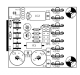
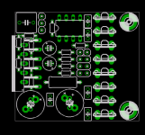
That's right, some of the resistor are underneath the LM3886.
The IC is elevated about 15mm above PCB level, so the resistors are inbetween it's legs.
Shortens the signal path and helps to optimize the layout.
Cheers,
Sebastian.
The IC is elevated about 15mm above PCB level, so the resistors are inbetween it's legs.
Shortens the signal path and helps to optimize the layout.
Cheers,
Sebastian.
sek said:The IC is elevated about 15mm above PCB level, so the resistors are inbetween it's legs.
Shortens the signal path and helps to optimize the layout.
Why not just use SMDs? 😉
That would be boring, as all GC projects before by myself here on diyaudio.com have been SMT, e.g. the two-channel module with included PSU measuring just 100mm x 80mm x 35mm (of which I continuously use two modules since april 2005)... 
No kidding, the project in question is intended for beginners and people who want to try a design that is easy to build. I basically just helped out with a PCB optimization.
After all, this thread is about a simple LM3886 amp, yet with variable preamp/buffer and volume control. It helps to make it as easy to build as possible. 😉
Cheers,
Sebastian.
It would be boring because all of the GC projects before you were SMT? On the contrary, the vast majority have used through hole components. I've only seen a few (including mine) that used SM components.
In all honesty I would have to say surface mount components are easier to solder than through hole components. It's just like soldering through hole components. Once you get the technique down you can do it no problem.
I'm not bashing your board in any way, in fact it looks like a very good single sided layout, if not a bit unconventional elevating the chip up off the board quite a bit to accomodate those large, bulky, through hole resistors 😉
Hi,
Oops, perhaps I wasn't clear. I wrote "GC projects before by myself here". By that I mean that I (myself) only made SMT GC projects before. Of course the vast majority of projects by others aren't. Sorry for the confusion, but I thought the words "by myself" would make it clear in English as they would in my language.
Again, this project is intended to use through-holes parts only - simply because the thread starter asked for assistance in such a project.
Thanks for the kind words. 😎
In fact, the through-hole resistors underneath the LM3886 aren't that bulky at all. The parts' size is '0204' with 5mm lead pitch. They have the actual parts body size of 1206 or regular mini-melf SMD resistors (minus the bent solder leads)! That's very small for through-hole parts. They're actually fitting inbetween the IC's pins nicely and comfortably, there's no trick and no cheating in mounting the IC above the resistors. My estimate of 15mm elevation above PCB level was a rough guess on the regular IC placement and does not indicate any special mounting (and maybe it's 10mm, that won't harm the resistors). You'd just have to take a little care with soldering. 😉
A nice technique practiced by many others who want short signal paths is to mount through-hole components from the solder side. This would help everyone out who is in doubt about resistor placement within this project. But you don't have to, trust me. 😉
Cheers,
Sebastian.
BWRX said:It would be boring because all of the GC projects before you were SMT? On the contrary, the vast majority have used through hole components. I've only seen a few (including mine) that used SM components.
Oops, perhaps I wasn't clear. I wrote "GC projects before by myself here". By that I mean that I (myself) only made SMT GC projects before. Of course the vast majority of projects by others aren't. Sorry for the confusion, but I thought the words "by myself" would make it clear in English as they would in my language.
Again, this project is intended to use through-holes parts only - simply because the thread starter asked for assistance in such a project.
I'm not bashing your board in any way, in fact it looks like a very good single sided layout, if not a bit unconventional elevating the chip up off the board quite a bit to accomodate those large, bulky, through hole resistors 😉
Thanks for the kind words. 😎
In fact, the through-hole resistors underneath the LM3886 aren't that bulky at all. The parts' size is '0204' with 5mm lead pitch. They have the actual parts body size of 1206 or regular mini-melf SMD resistors (minus the bent solder leads)! That's very small for through-hole parts. They're actually fitting inbetween the IC's pins nicely and comfortably, there's no trick and no cheating in mounting the IC above the resistors. My estimate of 15mm elevation above PCB level was a rough guess on the regular IC placement and does not indicate any special mounting (and maybe it's 10mm, that won't harm the resistors). You'd just have to take a little care with soldering. 😉
A nice technique practiced by many others who want short signal paths is to mount through-hole components from the solder side. This would help everyone out who is in doubt about resistor placement within this project. But you don't have to, trust me. 😉
Cheers,
Sebastian.
Attachments
- Status
- Not open for further replies.
- Home
- Amplifiers
- Chip Amps
- LM3886 - P19, Any comment?