Hi,
Just as a sidenote to the topic: Why is it that numerous people use their eCAD software for making boards without starting from the schematic?
It defeats most of the purposes of, e.g., Eagle. You would be quicker with a drawing program like Illustrator - or even Paint - if You consider the learning curve. Some of the features You're really missing:
- abstraction between component functionality and physical package (packages can be exchanged while always maintaining electrical correctness),
- electrical "rule checking" (schematics can be tested for plausibility and corrected independent of board layout),
- physical "rule checking" (board layout can be adjusted independent of electrical schema),
- maintainability (schematic or board can evolve and become improved while never risking errors in other parts of the respective other files),
just to name a few... Besides that, discussing it on a forum would be a lot easier (if we had Your schematic that explicitly matches Your board) as Nordic already said.
Just my two cents, have fun!
Sebastian. 😉
PS: I understand that P19 is ESP's Project 19, a Chipamp that Rod Elliot made a couple of years ago, inspired by Siegfried Linkwitz's excellent amplifier project.
But still, how should we check your board against Rod's schematic. That's what Your computer is for... 😉
edit: PS
numerous people use their eCAD software for making boards without starting from the schematic
Maybe roly3055 does have a schematic and just didn't post a screenshot?
Why is it that numerous people use their eCAD software for making boards without starting from the schematic?
Because the schematic is so simple or common.
It's not about complexity.
My point is: would the original poster have used a schematic in Eagle, his question could narrow down to layout beauty doubts. Electrical correctness is hard to verify on a board by looking at it. Before the question wether the board is good comes the question: Was the well-known schematic applied correctly.
Tools are there to rule out this uncertainty, and they are free and in the hands of the poster. 😉
Hi roly,
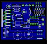
to contribute to your question: Your power rail traces have 'regular' with, which is too narrow in this case. Make them as wide as possible, there's no need to keep a ground plane as far as to the chip.
Eagle has 'faston' connectors (which you seem to try to resemble with jumpers) in the library 'con-rib'. The 6.3mm vertical connector is named 'ST6,3', for example.
Try experimenting with larger filter capacitor packages or wider footprints (e.g. 7.5mm or 10mm), which are also available form many parts suppliers. Also, those caps look a little small for the purpose, but you might of course go with the 1000uF approach. 😉
You also micht want to have a read about snubbed supplies for chipamps (just do a search for snubberized gain clones). You can increase filter capacitance while improving the sound, according to many DIYers.
What does LSP2 do? It might sit in an uncomfortable place. I won't stress that I knew if I had a schematic. 😀
Cheers,
Sebastian.

As sek suggested, use fast on tabs or through holes for wire connections. You can make your own, use the ones in the library, or find a nice terminal block footprint. I prefer to have the option to use terminal blocks for power, ground, and speaker connections.
Thicker power and speaker traces would be good (also as sek suggested).
I would suggest moving your volume pot in front of the opamp input buffer along with the coupling cap. This has a number of advantages. Now you can get rid of R6, C1, and C4 and change R9 to a 1kohm resistor. It will allow the low output impedance of the buffer to directly drive the input of the 3886 with better results. It also means you can use a smaller value coupling cap due to the higher input impedance of the buffer. You can now change the layout a bit to make the signal trace much shorter and have a more direct route from IC1 to the 3886 input pin. Also, add a ground connection alongside the +/- supply connections for the buffer supply.
Allright, LSP2 is signal ground.
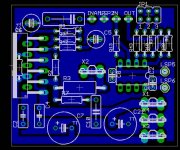
You include a buffer and a pot connection with your chip amp. That's not Project 19. Which is why I rumbled in the first place. 😉
Cool idea with the jumpers to set the input stage gain.
You won't need two DC blocking caps around the volume potentiometer, one at the input side of the amp section (as in P19) will be sufficient.
220uF for supply buffering is definitely too little for a 24V supply and 4-16Ohm speakers, except you use separate supply regulation/filters (which P19 requires). Other than that, it works good to have both filter caps at the same side of the chip.
As you have the buffer/preamp onboard, I would recommend a star grounding scheme instead of a ground plane. You have a ground loop around your preamp section, and the copper that connects signal ground to power ground also shares current flow with the poweramp section.
Also, you don't seem to connect the preamp supply's ground onboard - which actually requires another ground star in the supply...
You left out the fuses. That's good as long as you're okay with that and take care of safety in the main power supply.
Increasing your R9 to 3k3 will increase input impedance and thus shift input bias a little. This could result in DC output, but you could give it a try like this and experiment with the value.
Your drawup of the jumpers and connectors looks a little odd! Did you hardwire the TL's supply by hand? Look at Eagle's 'invoke' command, either in the toolbar or as a console command. It lets you place the opamp's power pins independent of the amp symbol. You didn't do that (or at least I can't seem to see it), which is why you had to be creative with the circuitry around J4/J5. 😀
Last, not least: I already pointed out the too thin traces for power and the missing scheme for ground. This would impact sound quality and fun the most, everything else I mention is peanuts compared to the power and ground layout and wiring problems you could have.
What project would you like to use it in?
Cheers,
Sebastian.
EDIT: Uh, Oh! I take it back. Brian's suggestion with the pot will influence the sound the most! (He was quicker typing than me 😉) But everything else is still important...
sek said:220uF for supply buffering is definitely too little for a 24V supply and 4-16Ohm speakers, except you use separate supply regulation/filters (which P19 requires).
If he plans to use larger bulk filter caps off the board then 220uF on board should be ok. A separate power supply just for the input buffer opamp would be best, but it is possible to make a simple regulated supply off of the higher voltage power supply rails with a handful of components. In the attached schematic in this post check out the components on the far right side. That's just a basic emitter follower with a zener reference that is used to derive the opamp's +/- supply rails from the higher voltage +/- supply rails.
sek said:As you have the buffer/preamp onboard, I would recommend a star grounding scheme instead of a ground plane. You have a ground loop around your preamp section, and the copper that connects signal ground to power ground also shares current flow with the poweramp section.
A ground plane is ok if you know where the currents will be flowing. If you don't then a star grounding scheme will force the currents to flow where you want them. If the opamp's rails are derived from the higher voltage supply rails then ground paths should all return to one point. If separate supplies are used then separate ground points may be used as long as they are connected to each other.
Okay, I start digging it. Finally.
Project 115 is reusing project 19, that's why the pot is in the middle. Rod did this because it's more simple, no other reason (as he writes himself).
It's also using parts of Project 88 for the preamp section.
Roly, there's no need for you to do so, unless you have project 19 and parts of project 88 at hand. 🙂
Have you had a look into e.g. Carlos' snubberized, buffered amplifier project?
@Brian,
of course I see your points, but all this is assuming a background Roly doesn't give us...
Cheers.
sek said:of course I see your points, but all this is assuming a background Roly doesn't give us...
True 🙂 I'm sure he'll give us more details sooner or later.
Many changes applied 🙂
A couple of things from first glance:
#
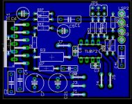
Look at the triangle between LSP2, J3 and the LM3886's ground pin. This is a loop. You have two power supplies and one signal cable. All three of them have one ground. All those three ground potentials have to be united somewhere. Currently, amp power ground and signal ground unite in a loop onboard and buffer supply ground is not shown. I'd suggest it would be better to have one star-like scheme where all three of them meet - either off- or onboard. This scheme may well be implemented as a ground plane, but a thin triangle is not a plane...
#
You could jump over the +24V trace with R7 and/or C10 in order to tie them directly to the power ground trace there.
#
After having played with R7/C10, try to move R3 a little lower and J7 to the very right side where the power connection is. This will help R42/C5 to free up this huge board area in the middle of the 'triangle'.
#
Now, move the TL072 a little to the left in order for the power connectors to line up properly at the right edge. Invoke the TL's power pins in order to model the power supply correctly.
#
Replace all jumpers with ST6,3 from 'con-rib'. Introduce another ST6,3 for the buffer supply ground and then another one for speaker return connection. Keep all those 'fast on' connectors 5mm apart, as anything more narrow is unsafe during testing and setup. You can even buy fast on block connectors in that spacing.
Now you're almost done. 😉
BTW, C1 looks a little small (you need between 1uF and 3.3uF; e.g. at least MKS 5.5x7mm or MKP 5x13mm), C2 and C4 look a little large (you can use the same type for C2, C3, C4, C8; e.g. 100nF/63V, 2.5x7.5mm). Also, C7 and C21 could be turned 45 degree by choosing 'rotate', clicking at the part and moving the mouse without releasing the mouse button... 😉
Cheers,
Sebastian.
A couple of things from first glance:
#
Look at the triangle between LSP2, J3 and the LM3886's ground pin. This is a loop. You have two power supplies and one signal cable. All three of them have one ground. All those three ground potentials have to be united somewhere. Currently, amp power ground and signal ground unite in a loop onboard and buffer supply ground is not shown. I'd suggest it would be better to have one star-like scheme where all three of them meet - either off- or onboard. This scheme may well be implemented as a ground plane, but a thin triangle is not a plane...
#
You could jump over the +24V trace with R7 and/or C10 in order to tie them directly to the power ground trace there.
#
After having played with R7/C10, try to move R3 a little lower and J7 to the very right side where the power connection is. This will help R42/C5 to free up this huge board area in the middle of the 'triangle'.
#
Now, move the TL072 a little to the left in order for the power connectors to line up properly at the right edge. Invoke the TL's power pins in order to model the power supply correctly.
#
Replace all jumpers with ST6,3 from 'con-rib'. Introduce another ST6,3 for the buffer supply ground and then another one for speaker return connection. Keep all those 'fast on' connectors 5mm apart, as anything more narrow is unsafe during testing and setup. You can even buy fast on block connectors in that spacing.
Now you're almost done. 😉
BTW, C1 looks a little small (you need between 1uF and 3.3uF; e.g. at least MKS 5.5x7mm or MKP 5x13mm), C2 and C4 look a little large (you can use the same type for C2, C3, C4, C8; e.g. 100nF/63V, 2.5x7.5mm). Also, C7 and C21 could be turned 45 degree by choosing 'rotate', clicking at the part and moving the mouse without releasing the mouse button... 😉
Cheers,
Sebastian.
sek said:BTW, C1 looks a little small (you need between 1uF and 3.3uF; e.g. at least MKS 5.5x7mm or MKP 5x13mm), C2 and C4 look a little large (you can use the same type for C2, C3, C4, C8; e.g. 100nF/63V, 2.5x7.5mm).
It's always difficult to do a proper layout when you aren't sure what parts you want to use 😉
the unused amplifier has no connections
literature recommends grounding of in+ and connecting in- to vout
I´ve always done this, so I´ve no experience with leaving the pins open.
maybe this could interfere with your circuit, maybe not
regards
literature recommends grounding of in+ and connecting in- to vout
I´ve always done this, so I´ve no experience with leaving the pins open.
maybe this could interfere with your circuit, maybe not
regards

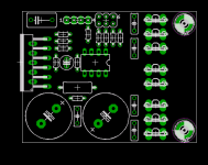
I was thinking of something like this, going even a step further. Especially the connectors and number of ground plugs.
The area right of the 6,3mm plugs could contain the central ground point (where the grounds meet). Also easily forgotten: mounting holes... 😀
Just a thought, anyway. How you do it is of course totally up to you.
Cheers.
The area right of the 6,3mm plugs could contain the central ground point (where the grounds meet). Also easily forgotten: mounting holes... 😀
Just a thought, anyway. How you do it is of course totally up to you.
Cheers.
Attachments
- Status
- Not open for further replies.
- Home
- Amplifiers
- Chip Amps
- LM3886 - P19, Any comment?