
Is it 30 volts split? 15 volts a rail? That will work, but power output will be limited.
15 volts single ended is too low.
30 amps? You could run multiple amplifiers off that transformer. Still, each one would have limited output power because of the low voltage.
It would be a good transformer maybe if you were trying to build a 1 ohm stable amplifier. It would be even better if you wanted to build a power supply to run a large car amplifier at home.
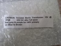
Guys, the advert on ebay, where i bought this said:
Can someone help me make sense of what this means?
Also, is this a single output or has secondary (tappings?) one too?
after full wave rectification you would have 22V DC
Can someone help me make sense of what this means?
Also, is this a single output or has secondary (tappings?) one too?
You can use 22V rails to run a chipamp but 30VA means you will be current limited. The 3886 will work fine. I use a pair of 18VA transformers to test chip amps all the time and with test speakers there is a reasonable amount of power.
You should still manage a dozen or so watts at reasonable quality.
If you have more than one you can parallel the secondaries. 60VA should be enough for a small boom box or bedroom system.
You should still manage a dozen or so watts at reasonable quality.
If you have more than one you can parallel the secondaries. 60VA should be enough for a small boom box or bedroom system.
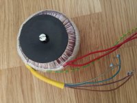
The wires are a clue.
The two reds are probably the mains primary.
The green/yellow may be a screen.
The four wires Blue, Brown, Violet & ? might be a dual secondary winding.
But because these have an extra sleeve of insulation they could be a dual primary, meaning the reds are a single secondary.
More information will help.
insert each wire end into separate terminals of a 7way insulated terminal block. The screw down should break through the enamel insulation.
Set your DMM to low ohms, preferably 199.9r
Measure resistance probe to probe.
measure red to red
G/Y to all other terminals
V to Bl
V to Br
V to ?
Bl to Br
Bl to ?
Br to ?
Post results of all 14 results.
Thanks AndrewT and others for your input. I will post more pics and test results once I receive the transformers. Waiting for the post at the momemnt.
Can someone help me with the maths in VAC to VDC?
VDC = 15VAC = 1.4?
15 x 1.4 = 22.5 VDC
What about amps?
I am assuming, 30VA = 30/15VAC = 2amp
so, is this correct for DC also?
30VA/22.5VDC = 1.33A DC?
1.3A is kinda low fo anything right?
Is there anything at all that I can build with this transformer?
a sinewave has an average and an rms equivalent and a peak value.
These are all different.
To convert a sinewave from ac or rms to peak you multiply.
Vpk = sqrt(2)*Vac or Vrms.
DC stored on a smoothing capacitor is not the peak of the AC waveform.
You need the Vac and convert that to Vpk. That passes through a rectifier. The rectifier drops a few hundred mV this is the Vf value shown in the datasheet. Typically for a silicon diode rectifier Vf~700mVf
Start with a 12Vac transformer.
You measure the output as 13.2Vac
Convert to 18.67Vpk
Subtract Vf to give 17.97Vdc if there is ONLY one diode drop.
Most rectifiers have TWO diode drops giving 17.27Vdc
Your DMM set to 20.00Vdc will read close to that value.
But that voltage is not fixed.
It varies with mains supply voltage.
It also varies with load current. and with diode Vf and with temperature and with ripple voltage.
All these have an effect on the voltage reaching your circuit.
Your circuit must be designed to tolerate that variable supply voltage.
A transformer is rated for AC into a resistive type load.
A 12Vac dual secondary transformer wound for universal use around the world will probably be specified as:
230:0-12, 0-12Vac 30VA 12% regulation, with dual 115 primaries
The 230 tells you the mains voltage.
The 0-12 tells you the secondary voltage on one output when the whole transformer is loaded with appropriate resistor loads on ALL windings.
The 30Vac tells you the load it can supply.
You can convert this to Amperes by dividing:
Iac = 30VA/ (12+12Vac) = 1.25Aac
This is the maximum continuous AC current that this transformer can pass. It will run at the designer's chosen maximum temperature, maybe 70C degrees above ambient in the hottest parts of the winding/core.
The 12% tells you how high the voltage will rise when the load is reduced to 0Aac and the input is still 115/230Vac.
You must not attempt to draw 1.25Adc continuously from this transformer.
The manufacturer will usually give guidance on acceptable DC currents after the various types of rectifier and smoothing that can be fitted. There is a LOT of VARIATION in maximum continuous DC current.
A mains transformer is a very robust piece of equipment.
It will survive undamaged from enormous short term overload abuse.
eg. flicking two secondaries together may pull a short term current 100times the rated 1.25Aac.
But if the "flick" is VERY SHORT TERM , then there will be no damage.
Some transformers have a built in (and usually inaccessible) thermal fuse. If this fuse opens the transformer is scrap !!!!!!!
Last edited:
I can understand grn to any of the others giving hay-wire results.
That would confirm that Grn is ONLY connected to screen.
Violet to brn and Blue to grey confirm these are tappings to different windings and each winding is ~43r. This is high indicating a lot of thin wire.
Probably the primary windings of a dual primary transformer.
The fact that none of Violet, Brown, Blue nor Grey connect to any other tap is good news. It means that at very low voltage there is no short from mains to any isolated winding.
But I can't understand why red to red does not give a valid resistance.
Check that again. and make sure the enamel is broken through.
")
- Status
- Not open for further replies.
- Home
- Amplifiers
- Chip Amps
- LM3886 - LINTRON Toroidal Transformer 15V @ 30VA??