I hooked it up to a power supply 28 VAC in and around 40Volt VDC out. C7 exploded immediately. C7 was 63V.
Could it be that I have d gone something wrong with the 47kohm rM? Reading the manual it sounded like it says a 47kohm across rM to disable the mute function. But I'm not sure.
c10 is in parallel with C5 and C4. whay is this? what does it do?
Did you read my article on supply decoupling? In the post quoted below, you thanked me for making it available and called it an "excellent read", so I'm thinking you did read it... The answer to your question is in that article. All you have to do is to look at the pictures...
This is an excellent read. Thank you for making this content and sharing it. So I can reduce c5 and c7 to 470 micro farad with no adverse effect and then install a ceramic and an electrolytic in parallel for c4 and c6, right?
rM is 470 Kohm to disable the mute function
That's not going to work. Recycling more content:
That looks like a copy of the Ti data-sheet and I expect all will be well to use the components suggested in the original;
https://www.ti.com/lit/ds/symlink/lm3886.pdf
If you're curious about how the mute circuit in the LM3886 works, you can also read my explanation of the topic: LM3886 Mute Circuit.
I understand that i seem to be asking the same questions and t might seem that I am trying to get all the answers from you guys without doing any experimentation or trying. the problem is that pretty much every time I have to desolder something that board and all those components go into trash.
You can find the answers to your questions in the LM3886 data sheet and in my Taming the LM3886 article series. Part of my reason making those articles available is to be able to help without retyping the same answers over and over.
if it is a component with three legs or any IC there is no chance, it is over.
Sounds like you should invest in a good de-soldering pump (aka solder sucker). I recommend the Jonard DP-200 (Mouser P/N: 801-DP-200). De-soldering braid (solder wick) helps too. I often use both.
so that is why i am asking you guys to check my board with pictures and schematic.
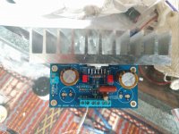
You have shown two different schematics. Neither of them matches the board you have. Thus, in order for me to help you, I have to redraw the schematic from your board pictures. That's impossible for me due to the glare from the flash. Even if I had the board in-hand, it would still take me a good half hour to do. That's more time than I'm willing to invest pro bono, in particular given your seeming unwillingness to read a website or a data sheet.
I'm more than willing to help you help yourself, however the "help yourself" is a key ingredient here. A good starting point would be to redraw the schematic so that it matches your PCB.
If you need a known-good bill-of-materials, I suggest you contact the eBay vendor. They should support their boards.
Tom
I hooked it up to a power supply 28 VAC in and around 40Volt VDC out. C7 exploded immediately. C7 was 63V.
You understand that the supply needs to be a bipolar supply, yes? You need ±10 to ±42 V. I highly recommend staying below ±30 V. You also need to provide the LM3886 with a heat sink.
Tom
The power supply is correct. It works fine with my lm3875 providing +-25. My lm3886 is fried and I already opened a return request to the seller of this board. Ofcourse the cost of the board is nothing compared to the components that are fried. I just want the seller to know his product has many problems
Attachments
Last edited:
I hooked it up to a power supply 28 VAC in and around 40Volt VDC out.
The power supply is correct. It works fine with my lm3875 providing +-25.
So the power supply simultaneously provides 40 V and ±25 V. I can't help you with that.
You're right that the seller should document his/her circuits better. Best of luck with your return request.
Tom
the power supply consists of an antek transformer that provides 28VAC translating to ~40VDC with no load after the two 10000 micro farad filtering capacitors, then when this power supply is connected to my LM3875, the DC voltage that I measure at the terminals of the LM3875 amplifier is +-25 VOLTS. this is the voltage at the load. do you need picture proof? I wont continue with this. thanks for the help though. very much appreciated.
Last edited:
No, but you might want to consider that I can't read your mind and sharpen up your communication accordingly. You don't say ±40 V anywhere, only "40 V". There is a difference.
If the supply voltage droops from ±40 V to ±25 V, there's something wrong or you're using way too little supply capacitance. I'd use at least 2x4700 µF plus the local decoupling on the amplifier board.
Tom
If the supply voltage droops from ±40 V to ±25 V, there's something wrong or you're using way too little supply capacitance. I'd use at least 2x4700 µF plus the local decoupling on the amplifier board.
Tom
No, but you might want to consider that I can't read your mind and sharpen up your communication accordingly. You don't say ±40 V anywhere, only "40 V". There is a difference.
If the supply voltage droops from ±40 V to ±25 V, there's something wrong or you're using way too little supply capacitance. I'd use at least 2x4700 µF plus the local decoupling on the amplifier board.
Tom
I see. these two filtering capacitors are 10000 micro farad nichicons, they are very very well used though. I got them used years ago and they have been continuously used for years. it is possible that they might have reduced capacity. i can check that using an ESR meter that I have. I will not continue with this project though.
I suggest checking the capacitance of those before using them in another project. Load them with 1 kΩ (use a 5 W type). Turn the power on. You should see nearly ±40 V. Turn the power off. It should take about 50 seconds for the caps to discharge to 0 V. If they discharge significantly faster than that, I'd toss them.
An even better test would be to measure the capacitance with a capacitance meter. Should be within ±20% of 10000 µF.
Best of luck.
Tom
An even better test would be to measure the capacitance with a capacitance meter. Should be within ±20% of 10000 µF.
Best of luck.
Tom
Will do. In my previous post i mentioned using an ESR meter to measure the capacitance, i meant this: LCR-T4 ESR Meter Transistor Tester Diode Triode Capacitance SCR Inductance M328 606098871258 | eBay
it has worked great so far and it is a great cheap capacitance meter. I will make a point to check the capacity of those caps. I also have another bipolar unregulated power supply specifically for LM3886 but it needs repair, that's why i used the old power supply from the LM3875. I already have new 50V and 63V caps for both of these power supplies and i will take care of that tonight. also the seller also refunded me for those boards. I should have stuck with the tried and true XY boards instead of taking a chance on this awful board.
it has worked great so far and it is a great cheap capacitance meter. I will make a point to check the capacity of those caps. I also have another bipolar unregulated power supply specifically for LM3886 but it needs repair, that's why i used the old power supply from the LM3875. I already have new 50V and 63V caps for both of these power supplies and i will take care of that tonight. also the seller also refunded me for those boards. I should have stuck with the tried and true XY boards instead of taking a chance on this awful board.
- Home
- Amplifiers
- Chip Amps
- LM3886 Inverting/Non-inverting on one PCB build